Review: Stickvise Needs A Place On Your Bench

Stickvise is a simple device for a simple problem. It holds a work piece while you work on it. Most obviously this means a PCB for soldering, but there’s a twist of versatility that will make it work for a wide range of needs. Being someone who has often used the roll-of-solder-to-hold-a-circuit-board-down trick, only to upset the apple cart when I run out solder, this is a great little tool to have within arm’s reach. For those that already have a PCB vise, how often do you need more than one? How rarely do you need something that large? And if you’re lucky enough to have a microscope for soldering this is a perfect fixture for moving a board to and from without adjusting the focus.

Details of the Design

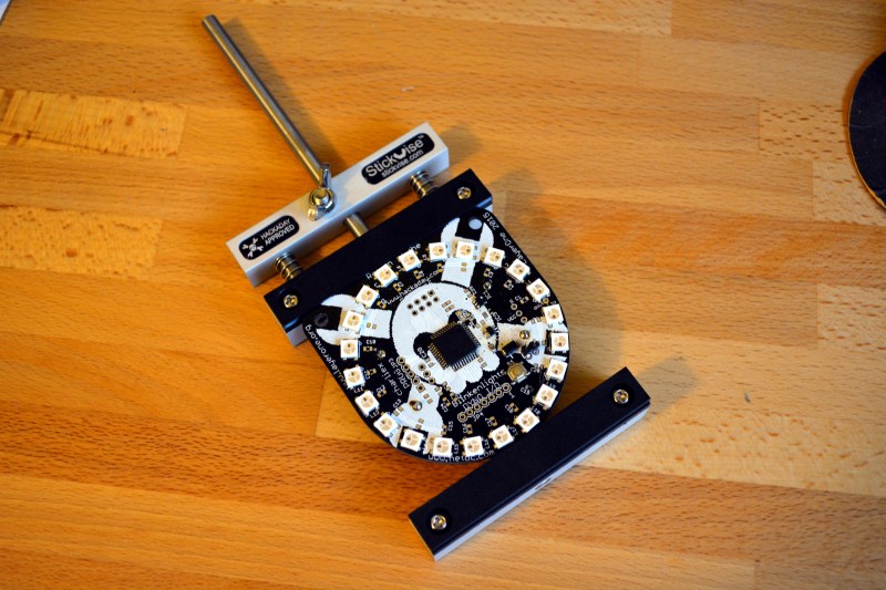
Simplicity. This is three pieces of aluminum bar-stock, some steel rod, nylon jaws, two springs, and some fasteners. It all works extremely well. To load up a new circuit board I loosen the wing nut and squeeze the clamp shut. Hand tightening the nut doesn’t take much force and it hasn’t slipped for me at all despite moving it around the bench for several days. Once set, the board can be taken out and flipped over easily thanks to the springs.

The extensibility here is key. As it stands, the nylon jaws have a V-groove to hold a board. If you need to support much taller boards you can always put some standoffs between the aluminum and the nylon jaws.
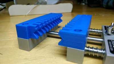
stickvise-custom-jawsBetter yet is the ability to design jaws for your own needs. [Alex Rich], Stickvise’s creator, already has a number of STL files available so that you may print out your own. The “fingers” on the custom jaw shown here interlock with the ones on the opposite side. But my favorite is an articulated set of “third-hand” style jaws based off of the PCB probe jig [Anool] covered back in May. There are even plans to make a parametric STL file so that printing larger or taller jaws doesn’t require a CAD modeling session.

If the range of the vise is too narrow you can simply replace the center bar with a longer one (source yourself or purchase from [Alex]) — the fixed aluminum end is secured with a set screw. This can even be used as a type of stretcher by reversing the spring jaw. I couldn’t think of an application in my own shop for this but you never know.

Stickvise Roots
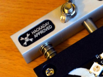
stickvise-hackaday-approvedIf you have an eagle eye you’ll have noticed the Jolly Wrencher with “Hackaday Approved” next to it on the Stickvise. When [Alex Rich] started refining his original design he posted about it as a project on Hackaday.io. It didn’t take long to grab our attention and, after tossing around the idea a bit we approached [Alex] about his plans for manufacturing and how Hackaday might figure into that. I love seeing hardware come to life like this; it puts an artisanal spin on the things I choose to have in my lab.

Conclusion
stickvise-angled

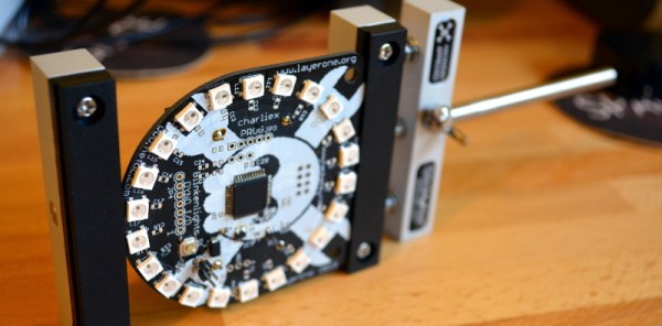
It’s so simple you could build it, but for me the production quality is well worth buying it instead. It’s simple and durable, with the ability to be specialized for a number of different purposes. I wish I had had it when populating the board I’ve been showing off in these pictures (the LayerOne Badge from this year). If you do any work with circuit boards at the bench the Stickvise is a solid entry on your must-have-tools list.

Bitten By PCB Defects

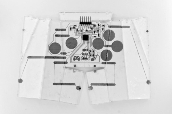
If you’ve ordered PCBs from Seeed Studio, ITead, DirtyPCB, or another board house in China, you’ve probably noticed that neat little 100% e-test option available on the order form. If you select this, the board house will throw your PCBs in a machine that will poke a pin in every pad to make sure all the connections are good. Less work for you, right? As [Andy] found out, not always. He was bitten by a manufacturing defect that sheds some light on what that e-test actually is, and the capabilities of what these Chinese board houses can do.

Most of [Andy]’s project have a lot of surface mount components, and when he receives his boards, he notices a few pin pricks on each and every pad. This is from a flying lead machine; a robotic continuity checker that makes sure all the relevant pads are electrically isolated from each other.

One of [Andy]’s recent projects is an entirely through-hole design. Apparently these robotic meters don’t test through-hole pads; it’s significantly harder to measure the continuity of a hole rather than a pad, apparently. After assembling one of these boards, he noticed a problem where one of the GPIOs was permanently high. The offending trace was found underneath a DIP socket, in precisely the worst possible place it could be.

If [Andy] had inspected the board beforehand, this problem would have been avoided. He says it was a relatively simple board with big traces and wide spaces and he didn’t think a manufacturing defect was possible. He was wrong, and now we have a warning. We thank him for that.

The Ultimate Tool For Homebrew PCB Manufacturing

While OSHPark, Seeed Studio, and DirtyPCB have taken most of the fun and urgency out of making your own circuit boards at home, there are still a few niche cases and weird people who like to go it alone. For them, [Jarzębski] has created the ultimate homebrew PCB manufacturing solution (.pl, here’s the Google translatrix).

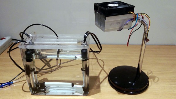
[Jarzębski] is using UV-sensitive photomasks for his PCBs, but he’s not doing something simple like a blacklight to develop his boards. He’s using a 30 Watt UV LED for exposing his boards. This, of course, generates a lot of heat and to mitigate that he’s added a Peltier cooler, temperature sensor, and a fan to cool off this retina-burning LED. 30 Watts will get the job done, considering [Jarzębski] was using a quartet of 4.5W LEDs before this build.

Developing a PCB is only one part of the equation; you need to etch it, too. For this, [Jarzębski] is using a small 1.6 Liter aquarium and four aquarium heaters for dunking 120mm x 120mm PCBs in the tank. There’s no mention of what chemistry [Jarzębski] is using – ferric chloride, cupric chloride, or otherwise – but the heaters and aerator should make etching go very smoothly.

There’s a video (English) going over the rest of the project below.

Continue reading “The Ultimate Tool For Homebrew PCB Manufacturing”

$50k In Play: Thirty Projects Will Win Custom PCBs This Week

This week we’re giving away $1500 in OSH Park codes to thirty different projects. Submit your project to the 2015 Hackaday Prize now!

$50,000 over the next 17 weeks!

official-submission-flagFor each of the last four weeks we’ve awarded prize packages to three projects just for submitting ideas. Now it’s time to crank up the rewards. Over the next 17 weeks we will give away $50,000 in prizes. We’re kicking off the week by giving $50 OSH Park codes to 30 different projects.
Of course this is just the tip of the iceberg. This year’s prizes total half a million dollars, with a trip into space for the Grand Prize winner and $100,000 for the Best Product prize. Sitting this one out would be a huge mistake!

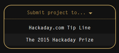
You need to post your project on Hackaday.io and officially submit it to the 2015 Hackaday Prize, which means clicking the “Submit-To” button on the left sidebar of your entry (shown below). You can confirm that you’re in the running by looking for the 2015 Hackaday Prize logo on your project gallery picture. Here you can see [castvee8] has submitted the Binary fuel tank, do you think it’s ready for a custom PCB?

Make it OfficialTo give yourself the best chance at winning, publish a new project log this week that outlines the PCB work your want to do for the entry. We’ll be looking for those as we judge the prizes that are most ready to begin (or advance) their hardware build.



OSH Park offers double-layer boards for $5 per square-inch and you get 3 copies of the board with shipping included. This $50 prize will land you quite a bit of board space. Get started now, you need to have your projects submitted by the morning of Wednesday, April 29th.


The 2015 Hackaday Prize is sponsored by:

A Automated Optical Inspection machine, inspecting the USB Armory board

Meet The Machines That Build Complex PCBs

You can etch a simple PCB at home with a few chemicals and some patience. However, once you get to multilayer boards, you’re going to want to pay someone to do the dirty work.

The folks behind the USB Armory project visited the factories that build their 6 layer PCB and assemble their final product. Then they posted a full walkthrough of the machines used in the manufacturing process.

The boards start out as layers of copper laminates. Each one is etched by applying a film, using a laser to print the design from a Gerber file, and etching away the unwanted copper in a solution. Then the copper and fibreglass prepreg sandwich is bonded together with epoxy and a big press.

Bonded boards then get drilled for vias, run through plating and solder mask processes and finally plated using an Electroless Nickel Immersion Gold (ENIG) process to give them that shiny gold finish. These completed boards are shipped off to another company, where a pick and place followed by reflow soldering mounts all the components to the board. An X-Ray is used to verify that the BGA parts are soldered correctly.

The walkthrough gives a detailed explanation of the process. It shows us the machines that create products we rely on daily, but never get to see.

Inexpensively Replace A Worn Out N64 Joystick

The Nintendo 64 is certainly a classic video game system, with amazing titles like Mario Kart 64 and Super Smash Bros that are still being played across the world today. But, like finding new parts for a classic car, finding an original controller that doesn’t have a sad, wobbly, worn-out joystick is getting to be quite the task. A common solution to this problem is to replace the joystick with one from a Gamecube controller, but the kits to do this are about $20USD, and if that’s too expensive then [Frenetic Rapport] has instructions for doing this hack for about $2.

The first iteration of using a Gamecube stick on an N64 controller was a little haphazard. The sensitivity was off and the timing wasn’t exactly right (very important for Smash Bros.) but the first kit solved these problems. This was the $20 kit that basically had a newer PCB/microcontroller that handled the Gamecube hardware better. The improvement which drove the costs down to $2 involves modifying the original PCB directly rather than replacing it.

While this solution does decrease the cost, it sacrifices the new potentiometer and some of the easier-to-work-with jumpers, but what was also driving this project (in addition to cost) was the fact that the new PCBs were becoming harder to get. It essentially became more feasible to simply modify the existing hardware than to try to source one of the new parts.

Either way you want to go, it’s now very easy to pwn your friends in Smash with a superior controller, rather than using a borked N64 controller you’ve had for 15 years. It’s also great to see hacks like this that come together through necessity and really get into the meat of the hardware. Perhaps we’ll see this controller ported to work with other versions of Super Smash Bros, too!

Hands-On Othermill Review Grinds Out Sparkling Results

We’ve been on the lookout for alternatives to chemically etching circuit boards for years. The problem has been that we don’t particularly want to devote months of or lives learning how to build precision CNC mills. Off in the distance there may be an answer for that quandary if you don’t mind parting with twenty-two Benjamins. Sure, it’s a heck of a lot more expensive than toner transfer and cupric chloride, but the Othermill can be purchased right now (in your hands a few months later) and after reading this in-depth review we are a bit less hesitant about opening our wallets for it.

othermill-review-thumbIt’s a tome of a review, but that means there’s something for everybody. We especially enjoyed seeing the 10 mil board shown here which took about 1-hour to mill. Considering it has also been through-hole drilled we’d put that on part with the time it takes to etch a board. There are obvious places where the traces are not perfectly smooth (not sure if that’s burring or over-milling) but they are not broken and the board’s ready to be populated.

Alignment is something of an issue, but the Othermill isn’t limited to PCBs so we’d recommend designing and milling your own alignment bracket system as an early project.

Who isn’t envious of custom-builds that can get down to 10-mils, like this beauty from 2013. Our hopes had been sparked when Carbide 3D came onto the scene. We’re still optimistic that they will make a big splash when they start shipping preorders in a few months.

As this review proves, Othermill is already out in the wild with a 6-8 week wait before shipping. We saw it in action milling multiple materials at the Hackaday Omnibus Lauch Party and were duly impressed. Price or waiting-period aside we’re going to hold off until the software options expand beyond Mac-only (UPDATE: Othermill software support for Windows was added in early 2016); either Othermill will add support or someone will come up with a hack to use traditional CNC software. But if you count yourself as a subscriber to the cult of Apple the software, called Otherplan, does get a favorable prognosis along with the hardware.

Already have an Othermill sitting on your bench? Let us know your what you think about it in the comments below.

Bonus content: [Mike Estee], CTO of Othermill just gave a talk last night about how he got into making mills and the challenges of building something with super-high-precision. Sound isn’t good but the talk is solid. Hackaday’s [Joshua Vasquez] also gives a talk on the video about building an SPI core for FPGA. These talks are one of the Hardware Developer’s Didactic Galactic series which you really should check out if you’re ever in the San Francisco area.

Continue reading “Hands-On Othermill Review Grinds Out Sparkling Results”