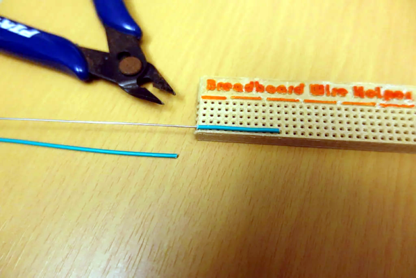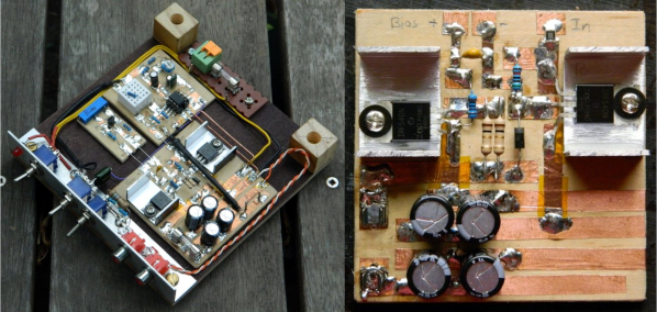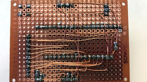
[Tom] doesn’t much like breadboarding. He prefers to wire up prototypes with perfboard and solder point-to-point with enameled magnet wire. That may sound troublesome to some of you, but [Tom] has come up with a few tips to make prototyping with perfboard and magnet wire easier and more effective, and the biggest tip is about how to manage stripping all that magnet wire.
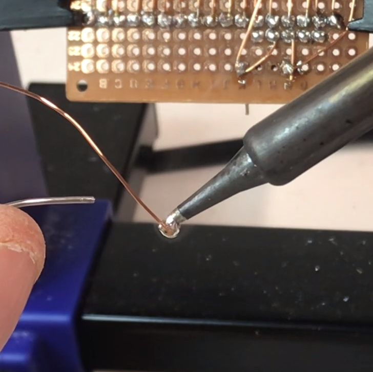
Magnet wire is a thin, solid-core conductor that has a clear coating of enamel. This enamel acts as an electrical insulator. The usual way to strip away the enamel and reveal the shiny copper underneath is to scrape it off, but that would get tiresome when working with a lot of connections. [Tom] prefers to “boil it away” with a blob of molten solder on an iron’s tip.
Begin by melting a small amount of solder on the iron, then push the tip of the magnet wire a small distance into the molten solder and hold it there for a few moments. The enamel will bubble away and the solder will tin the copper underneath in the process. The trick is to use fresh solder, and to clean the tip in between applications. You can see him demonstrate this around the 1:00 mark in the video embedded below.
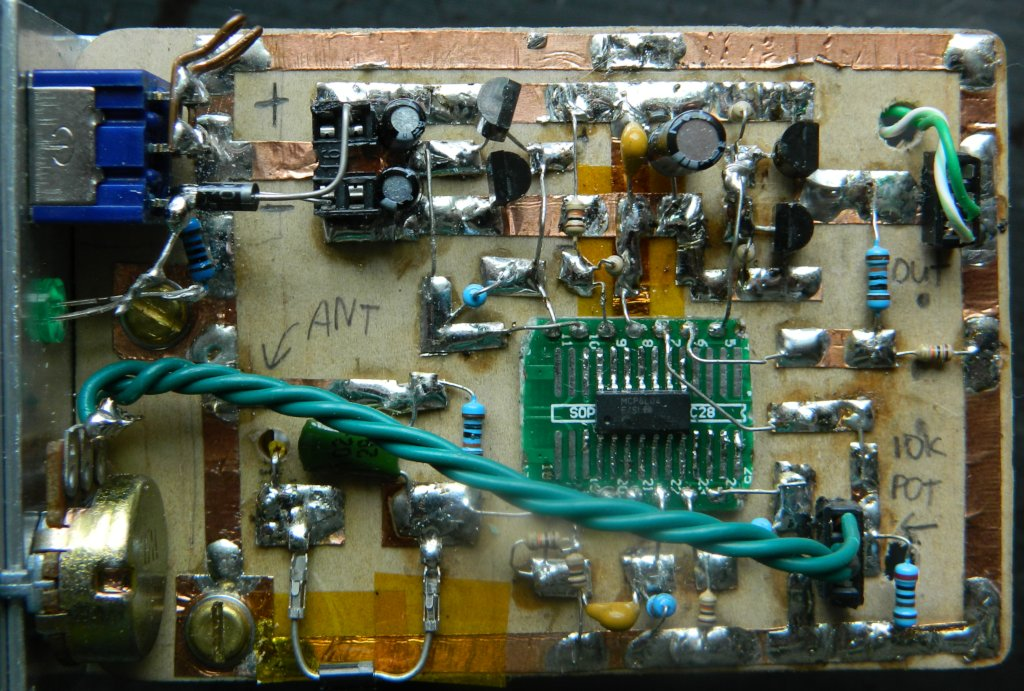
Once the tip of the magnet wire is tinned, it can be soldered as needed. Magnet wire bends well and holds its shape nicely, so routing it and cutting to size isn’t too difficult. [Tom] also suggests a good hands-free PCB holder, and points out that 0603 sized SMT resistors fit nicely between a perfboard’s 0.1″ pads.
Perfboard (and veroboard) have been standbys of prototyping for a long time, but there are still attempts at improving them, usually by allowing one to combine through-hole and surface-mount devices on the same board, but you can see [Tom] demonstrate using magnet wire on plain old perfboard in the video below.
Continue reading “Don’t Scrape Magnet Wire, Do This Instead”