Replacement PCB Replicates Early 80s Modem

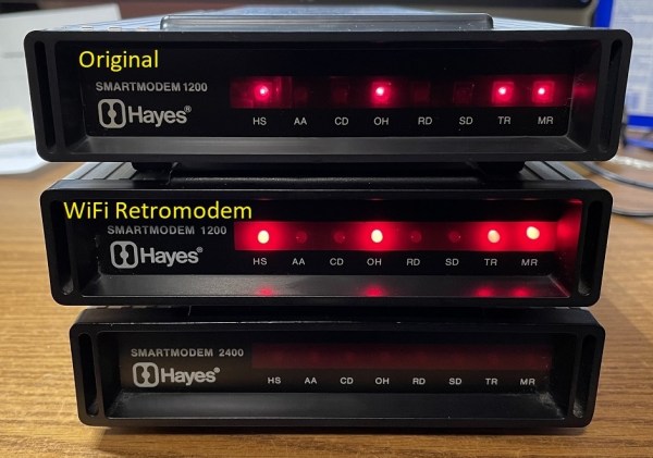
It’s certainly been a few decades, but plenty of us remember a time before widespread access to broadband internet, when connections were generally made over phone lines using acoustic modems. In the 90s these could connect you to AOL and Napster well enough, but in the early 80s the speeds were barely enough to read text as it loaded. A company called Hayes set out to change this with some of the first useful, widely-available modems for the PCs at the time. While they couldn’t keep up with the changing times there’s still a retro community that has these antiques, and to modernize it a bit this drop-in replacement for the PCBs replicates these old modems almost exactly.

The new PCB is equipped with everything needed to get a retro computer online again, including all the ports to connect a computer without any further modifications. It houses a few modern upgrades beyond its on-board processors, though. Rather than needing an actual acoustic coupled phone, this one has an ESP32 which gives it wireless capability. But the replacement PCB maintains the look and feel of the original hardware by replicating the red status LEDs at the front, fitting into the original Hayes cases with no modifications needed at all, and even includes a small speaker through which it can replicate the various tones, handshakes, and other audio cues that those of us nostalgic for this new online era remember quite well.

For those looking for a retro feel without the hassle of getting antique networking equipment functional again, this type of upgrade that preserves the essence of the original hardware is an excellent way of keeping retro computers functional on modern networking equipment. But if you absolutely must get the networking equipment exactly right down to the last patch cable, you might end up having to build your own ISP from scratch.

Continue reading “Replacement PCB Replicates Early 80s Modem”

Old Prius Gets Upgraded Batteries

So many of the batteries made today are lithium batteries of some sort, from mobile phones, laptops, and drones to electric cars and grid storage solutions. But this technology is relatively new; even as late as the 90s and early 00s the only widely-available batteries for things like power tools or the new hybrid vehicles coming on the market were nickel-metal hydride (NiMH). While it was good for the time, they don’t hold up to all of the advantages lithium has. There’s still plenty of hybrid vehicles on the road using these batteries, so if you’re driving an older Prius and want to give it a modern refresh, there’s a quick option to swap your old batteries.

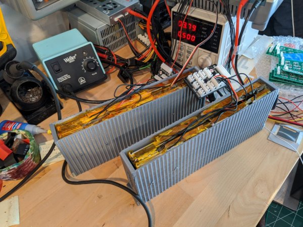
Despite lithium technology being available for several decades, the switch to lithium for the Toyota Prius wasn’t instant, with many variants still using NiMH batteries as late as the 2020s largely because the NiMH batteries are less expensive and less maintenance-intensive than lithium batteries are. As these batteries lose capacity, the cars are still driveable but the advantages of the hybrid drivetrain won’t be as accessible anymore. The upgrade, from a company called Project Lithium, replaces these batteries with modern lithium technology that can improve the efficiency and performance of these cars even above their original capabilities since lithium batteries have more power density.

With the Toyota Prius being among the most reliable vehicles on the road thanks to the electric motor in the hybrid drivetrain taking a lot of stress off of the internal combustion engine, it’s often worth upgrading these old batteries to modern ones to squeeze every last mile from these workhorses as possible. With many of the replacement processes being almost as simple as lifting out an old battery and placing a new one in, it can be a no-brainer if that’s the only issue with the vehicle otherwise. This is also true of all-electric vehicles as well, although the process to replace the battery can be a little more involved.

Thanks to [JohnU] for the tip!

Vintage HP-25 Calculator Gets Wireless Charging

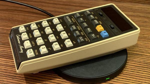
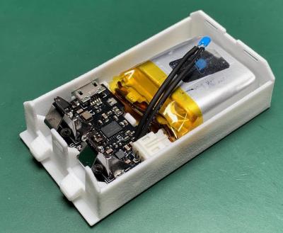
[Jan Rychter] really likes his multiple HP-25C calculators, but the original battery pack design is crude and outdated. No problem — he whips up a replacement using Fusion 360 to design an enclosure, prints a few on his SLS 3D printer, and packs them with LiPo batteries and Qi/WPC wireless charging circuits.

In his blog post, he explains the goals and various design decisions and compromises that he made along the way. We like [Jan]’s frank honesty as he remarks on something we have all been guilty of at one time or another:

In the end, I went with design decisions which might not be optimal, but in this case (with low power requirements) provide acceptable performance. In other words, I winged it.

One problem which proved difficult to solve was how to provide a low battery indicator. Since low voltage on a LiPo is different from the original HP-25’s NiCad cells, it wasn’t straightforward, especially since [Jan] challenged himself to build this without using a microcontroller. He discovered that the HP-25’s internal low battery circuit was triggered by a voltage of 2.1 volts or lower.

In a really clever hack, [Jan] came up with the idea of using an MCU reset supervisor chip with a low voltage threshold of 3.0 volts, which corresponds with the low voltage threshold of the LiPo battery he is using. The reset signal from the supervisor chip then drives one of the pins of the TPS62740 programmable buck converter, changing its output from 2.5 volts to 2.1 volts.

This project is interesting on several levels — extending the life of a useful but end-of-life calculator, improving the original battery design and introducing new charging techniques not available in the early 1970s, and it is something that a hobbyist can afford to do in a home electronics lab. We do wonder, could such a modification could turn an HP-25 into an HP-25C?

We’ve written about battery pack replacement project before, including one for the Sony Discman and another for an electric drill. Let us know if you have any battery pack replacement success (or failure) stories in the comments below.

Burned Out SKR E3 Mini Gets New Stepper Driver

It didn’t take long to figure out that a dead X axis and an message saying “TMC CONNECTION ERROR” meant that one of the stepper drivers on the SKR E3 Mini 3D printer control board had released the magic smoke. Manufacturer BigTreeTech replaced the board under warranty, and the printer was back up and running in short order. But instead of tossing it in the trash, [Simon] wondered how hard it would be to repair the dead board.

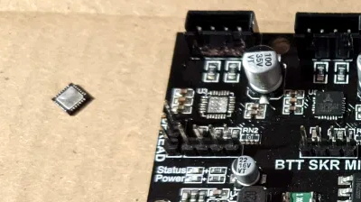
Removing the original stepper driver IC.

The short answer is, not very hard. There was no question as to which of the four TMC2209 drivers was shot, since the X motor was the only one experiencing a problem. The drivers unfortunately aren’t socketed on this board, but after a little kiss with the hot air, the old chip was off.

[Simon] didn’t have any spare TMC2209 chips, but the TMC2208 has the same pinout and is a drop-in replacement. The TMC2208 is rated for a bit less current, but it shouldn’t be a problem under normal circumstances.

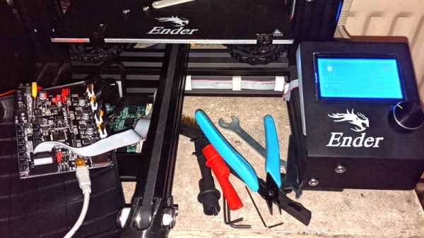
Other than the stepper connector getting a little toasty during the installation, the swap went off without a hitch and the board was up and running again. [Simon] ended up putting the now repaired SKR E3 Mini in his Ender 3; a nice 32-bit upgrade compared to the ATmega1284 that was originally running the show. Though in the past, he’s managed to squeeze a bit more performance out of the older 8-bit board as well.

Logitech Joystick Gets A Mechanical Sidekick

The mechanical keyboard rabbit hole is a deep one, and can swallow up as much money and time as you want to spend. If you’ve become spoiled on the touch and responsiveness of a Cherry MX or other mechanical switch, you might even start putting them on other user interfaces as well, such as this Logitech joystick that now sports a few very usable mechanical keys for the touch-conscious among us.

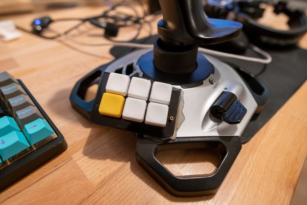
The Logitech Extreme 3D Pro that [ErkHal] and friend [HeKeKe] modified to accept the mechanical keys originally had a set of input buttons on the side, but these were unreliable and error-prone with a very long, inconsistent push. Soldering some mechanical switches directly on the existing board was a nice improvement, but the pair decided that they could do even better and rolled out an entire custom PCB to mount the keys more ergonomically. The switches are Kailh Choc V2 Browns and seem to have done a great job of improving the responsiveness of the joystick’s side buttons. If you want to spin up your own version, they’ve made the PCBs available on their GitHub page.

While [ErkHal] notes the switches aren’t the best and were only used since they were available, they certainly appear to work much better than what the joystick shipped with originally. In fact, we recently saw similar switches used to make a custom mechanical keyboard made for the PinePhone.

Bringing An IPod To The Modern NAND Era

Flash storage was a pretty big deal back in the mid ’00s, although the storage sizes that were available at the time seem laughable by today’s standards. For example, having an iPod that didn’t have a spinning, unreliable hard drive was huge even if the size was measured in single-digit gigabytes, since iPods tended to not be treated with the same amount of care as something like a laptop. Sadly, these small iPods aren’t available anymore, and if you want one with more than 8GB of storage you’ll have to upgrade an old one yourself.

This build comes to us from [Hugo] who made the painstaking effort of removing the old NAND flash storage chip from an iPod Nano by hand, soldering 0.15mm enameled magnet wire to an 0.5mm pitch footprint to attach a breakout board. Once the delicate work was done, he set about trying to figure out the software. In theory the iPod should have a maximum addressable space of 64 GB but trying to get custom firmware on this specific iPod is more of a challenge and the drives don’t simply plug-and-play. He is currently using the rig for testing a new 8GB and new 16GB chip though but it shows promise and hopefully he’ll be able to expand to that maximum drive size soon.

The build is really worth a look if you’re into breathing new life into old media players. Sometimes, though all these old iPods really need to get working again is just to be thrown into a refrigerator, as some genius engineer showed us many years ago.

Homemade Magic Makes The Metcal Go

First soldering irons are often of the Radioshack or Maplin firestarter variety. They’re basically wall power shorted across a nichrome heater or similar with some inline resistance to make it harder to burn down the house. You plug them in, the current flows, and they get hot. Done.

If you stick with the hobby for a while, these eventually get replaced with something like the venerable HAKKO FX-888D or that one Weller everyone likes with the analog knob. These are much improved; having temperature control leads to a more consistently heated tip and much improved soldering experience.

Entering the electronics workplace one comes across the next level of quality soldering iron: high end HAKKOs, Metcals, JBCs, and the like. Using one of these irons is practically a religious experience; they heat in a flash and solder melts while you blink. They even turn off when you put the handpiece down! But they’re expensive to buy (hint: think used). What’s a hobbyist to do?

[SergeyMax] seems to have had this problem. He bit the bullet, figured out how the Metcal works, and made his own base. This is no mean feat as a Metcal might look like a regular iron but it’s significantly more complex than ye olde firestarter. The Metcal magic is based on a oscillating magnetic fields (notice the handpiece is connected via BNC?) interacting with a tip bearing a special coating. In the presence of the changing field the tip heats up until it hits its Curie temperature, at which point it stops interacting with the magnetic field and thus stops heating.

When the user solders, the tip cools by sinking its heat into the part and drops below the Curie temperature again, which starts the heating again. It’s like temperature control with the sensor placed absolutely as close to the part as possible and a nearly instant response time, without even a control loop! [SergeyMax] has a much more thorough description of how these irons work, which we definitely recommend reading.

So what’s the hack? Based on old schematics and some clever reverse engineering from photos [SergeyMax] built a new base station! The published schematic is as rich with capacitors and inductors as one could hope. He didn’t post source or fab files but we suspect the schematic and photos of the bare board combined with some tinkering are enough for the enterprising hacker to replicate.

The post contains a very thorough description of the reverse engineering process and related concerns in designing a cost efficient version of the RF circuitry. Hopefully this isn’t the last Metcal replacement build we see! Video “walkthrough” after the break.

Edit: I may have missed it, but eagle eyed commentor [Florian Maunier] noticed that [SergeyMax] posted the sources to this hack on GitHub!

Continue reading “Homemade Magic Makes The Metcal Go”