Back when he was about seven years old, [Ytai] learned to program on an Atari 800XL. Now he has a seven-year-old of his own and wants to spark his interest in programming, so he created these programmable LEGO bricks with tiny embedded microcontrollers. This is probably one of the few times that “bricking” a microcontroller is a good thing!
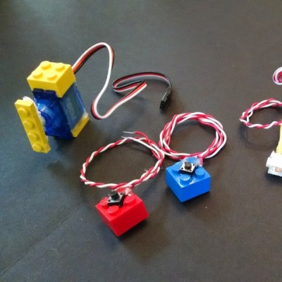 The core of the project is the Espruino Pico microcontroller which has the interesting feature of running a Java stack in a very tiny package. The Blocky IDE is very simple as well, and doesn’t bog users down in syntax (which can be discouraging to new programmers, especially when they’re not even a decade old). The bricks that [Ytai] made include a servo motor with bricks on the body and the arm, some LEDs integrated into Technic bricks, and a few pushbutton bricks.
We always like seeing projects that are geared at getting kids interested in creating, programming, and hacking, and this certainly does that! [Ytai] has plans for a few more LEGO-based projects to help keep his kid interested in programming as well, and we look forward to seeing those! If you’re looking for other ways to spark the curiosity of the youths, be sure to check out the Microbot, or if you know some teens that need some direction, perhaps these battlebots are more your style.