Wifi Antenna

Simple Directional WiFi Antenna

Back in 2007, [Stathack] rented an apartment in Thailand. This particular apartment didn’t include any Internet access. It turned out that getting a good connection would cost upwards of $100 per month, and also required a Thai identification card. Not wanting to be locked into a 12-month contract, [Stathack] decided to build himself a directional WiFi antenna to get free WiFi from a shop down the street.

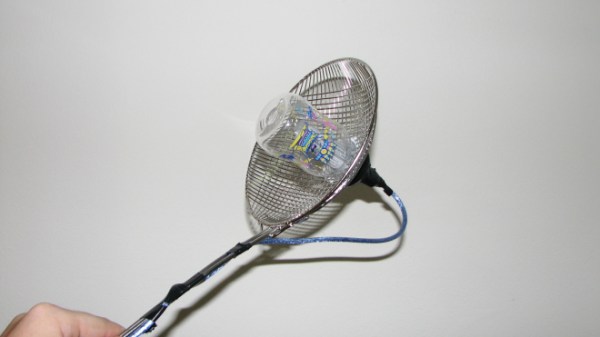
The three main components of this build are a USB WiFi dongle, a baby bottle, and a parabolic Asian mesh wire spoon. The spoon is used as a reflector. The parabolic shape means that it will reflect radio signals to a specific focal point. The goal is to get the USB dongle as close to the focal point as possible. [Stathack] did a little bit of math and used a Cartesian equation to figure out the optimal location.

Once the location was determined, [Stathack] cut a hole in the mesh just big enough for the nipple of the small baby bottle. The USB dongle is housed inside of the bottle for weatherproofing. A hole is cut in the nipple for a USB cable. Everything is held together with electrical tape as needed.

[Stathack] leaves this antenna on his balcony aiming down the street. He was glad to find that he is easily able to pick up the WiFi signal from the shop down the street. He was also surprised to see that he can pick up signals from a high-rise building over 1km away. Not bad for an antenna made from a spoon and a baby bottle; plus it looks less threatening than some of the cantenna builds we’ve seen.

DIY Optoisolator

MacGyvered Optoisolator Is A Great Introduction

Sometimes the best way to learn about a technology is to just build something yourself. That’s what [Dan] did with his DIY optoisolator. The purpose of an optoisolator is to allow two electrical systems to communicate with each other without being electrically connected. Many times this is done to prevent noise from one circuit from bleeding over into another.

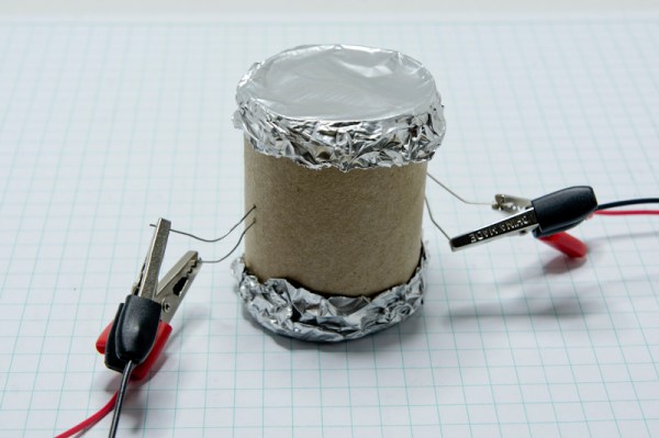
[Dan] built his incredibly simple optoisolator using just a toilet paper tube, some aluminum foil, an LED, and a photo cell. The electrical components are mounted inside of the tube and the ends of the tube are sealed with foil. That’s all there is to it. To test the circuit, he configured an Arduino to send PWM signals to the LED inside the tube at various pulse widths. He then measured the resistance on the other side and graphed the resulting data. The result is a curve that shows the LED affects the sensor pretty drastically at first, but then gets less and less effective as the frequency of the signal increases.

[Dan] then had some more fun with his project by testing it on a simple temperature controller circuit. An Arduino reads a temperature sensor and if the temperature rises above a certain value, it turns on a fan to cool the sensor off again. [Dan] first graphed the sensor data with no fan hooked up. He only used ambient air to cool things down. The resulting graph is a pretty smooth curve. Next he hooked the fan up and tried again. This time the graph went all kinds of crazy. Every time the fan turned on, it created a bunch of electrical noise that prevented the Arduino from getting an accurate analog reading of the temperature sensor.

The third test was to remove the motor circuit and move it to its own bread board. The only thing connecting the Arduino circuit to the fan was a wire for the PWM signal and also a common ground. This smoothed out the graph but it was still a bit… lumpy. The final test was to isolate the fan circuit from the temperature sensor and see if it helped the situation. [Dan] hooked up his optoisolator and tried again. This time the graph was nice and smooth, just like the original graph.

While this technology is certainly not new or exciting, it’s always great to see someone learning by doing. What’s more is [Dan] has made all of his schematics and code readily available so others can try the same experiment and learn it for themselves.


Retrotechtacular: Upgrading Train Signaling Before The Information Age

retrotechtacular-british-railway-signaling

What’s surprising about the subject of this week’s Retrotechtacular is that the subject is not from that long ago. But looking at the way in which the work was done makes it feel so far in the past. In 1974 the British Railways Board set out to modernize and interconnect the signaling system. What you see above is one of hundreds of old signal control houses slated to be replaced by an interconnected system.

These days we take this sort of thing for granted. But from the start of the project it’s clear how the technology available at the time limited the efficiency of the development process. We’re not talking about all of the electro-mechanical parts shown during the manufacturing part of the video. Nope, right off the bat the volumes of large-format paper schematics and logic diagrams seem daunting. Rooms full of engineers with stacks of bound planning documents feel alien to us since these days even having to print out a boarding pass seems antiquated.

With fantastic half-hour videos like this one available who needs television? We’d recommend adding this to your watch list so you can properly enjoy it. They show off everything; manufacturing the cables, stringing them between the signal towers, assembling the control panels, testing, and much more.

Continue reading “Retrotechtacular: Upgrading Train Signaling Before The Information Age”

Scratch-built Railroad Crossing Signal

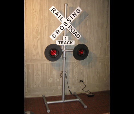
At first glance you would think this is the real thing, but [Kevin] built this railroad crossing signal from parts you can find at the home store. We keep seeing traffic lights used as web-connected signaling devices. This would be right at home for that type of setup, but [Kevin] built it with railroad enthusiasts in mind.

He used Google SketchUp to design the frame for the signal, then purchased all of the PVC parts to match those specifications. Some grey spray paint goes a long way to making it look like steel tubing. But this is much easier to work with and he should have no trouble internalizing the wiring later on. The lights themselves are tail lights for a trailer with a decorative trim piece added. He designed his own driver board to switch the lights and ring the doorbell which give the signal some sound. His first version used a 555 timer, this one upgrades to microcontroller. We like what he’s doing in the video after the break, but think the bell speed needs to be doubled for it to mimick the real thing just about perfectly.

Continue reading “Scratch-built Railroad Crossing Signal”

Pure TTL Based Clock

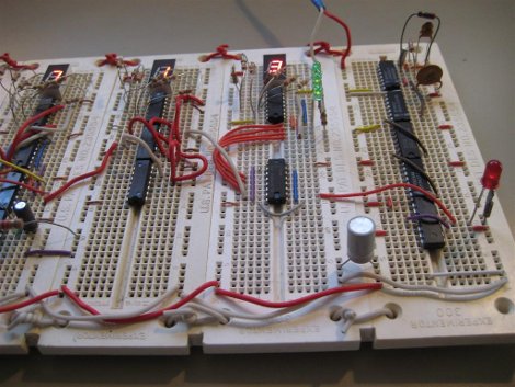
We’ll just say, [Kenneth] really likes clocks. His most recent is a pure 7400 series TTL based one, ie no microcontroller as seen in the past, here, here, and here. The signal starts out as a typical 32,768 crystal divided down to the necessary 1Hz, which is then divided again appropriately to provide hours and minutes.

As far as TTL clocks go, this is nothing too original; until it comes to his creative button interface. By using a not as sexy as it sounds multivibrator, he can produce a clean square wave instead of the figity signals produced from buttons to advance and set the time. Like always, he also provides us with a thorough breakdown of his clock, after the jump. Continue reading “Pure TTL Based Clock”

Use An Analog Oscilloscope To Display Digital Logic

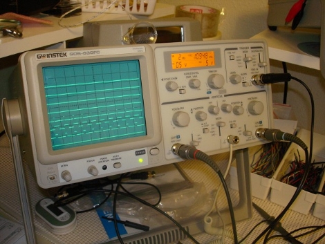
[Mike Bradley] wanted to use his oscilloscope to display 8 channels of digital signals. Alas, the analog unit didn’t have this capability. Not to worry, he threw together an adapter module that does the trick. Using a PIC 18F26K20 microcontroller he inputs four or eight channel digital logic (at 5V) and filters the output to an analog signal that the oscilloscope can interpret. What you see in the photo above is the result.

Arduino Traffic Light

[Rockwell] sent us an update on his traffic light hacking. Dedicated readers will remember seeing this legally attained traffic signal controlled through a parallel port from back in 2005. The new update swaps the old port for USB and adds several autonomous functions which are demonstrated in the clip after the break. The update includes a nice UI and some notifications for things like email, IMs, Reddit posts, etc.

He’s given control of the hardware over to an Arduino. Instead of building the board into the project he’s included just the parts he needs; an AVR running the Arduino bootloader, a crystal and filtering caps, and an Arduino serial to USB module for connectivity. The AC load switching is handled by three relays. The relays he links to are 12VCD rated coils. We think this should have pointed to 5VDC coils as that’s the voltage that the logic circuit are running at. Be careful with switching these AC loads, this traffic light isn’t a toy.

Continue reading “Arduino Traffic Light”