It was an American ritual for over four decades: wake up early on Saturday morning, prepare a bowl of sugar, and occupy the couch for four glorious hours of cartoons. The only interruptions came when the least-significant sibling had to be commanded to get up to change the channel to one of the two other networks, or when your mom decided to vacuum the TV room. It was a beautiful ritual, but now it’s gone.
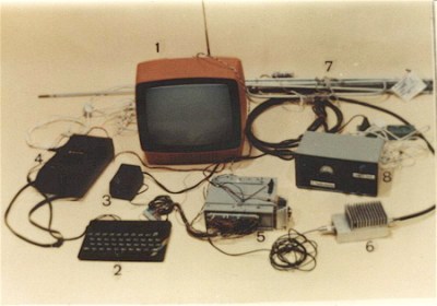
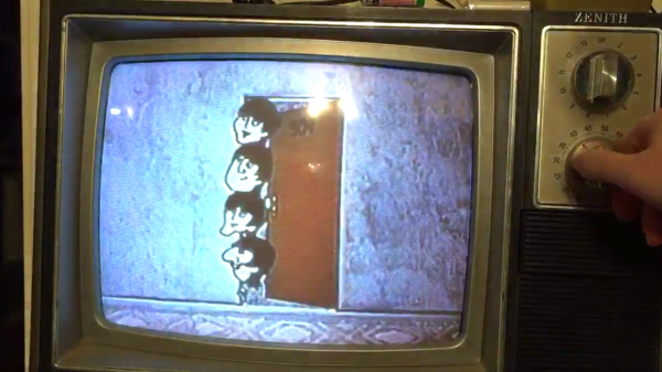
Or is it? If you really want to recapture your misspent youth, you can try this Raspberry Pi multi-channel cartoon server with retro TV display. [FozzTexx] started with a yard sale 13″ Zenith set, which languished in his shop for want of a mission. When he found a four-channel video modulator, he knew he had the makings of the full channel-changing Saturday morning experience.
Four Raspberry Pis were configured to serve up four separate streams of cartoons from his Plex server, and after a late Friday night of hacking the whole thing together, each stream was ready to go live at 7:00 AM on Saturday. [FozzTexx] thought of everything — from the pre-“broadcast day” test pattern to actual commercials spliced into the cartoons to the static between the channels, it’s all there in low-definition glory. He even printed up faux TV Guide pages! You can watch a brief demo on [FozzTexx]’ Twitter feed, or you can watch the entire 2-hour Periscope feed if you’re feeling nostalgic.
[FozzTexx] chose UHF channels for his “stations,” so if you want to replicate this build it may pay to bone up on analog TV tuner basics. Or if it’s just the retro look you’re going for, this custom case inspired by a 40s TV might be nice to check out.
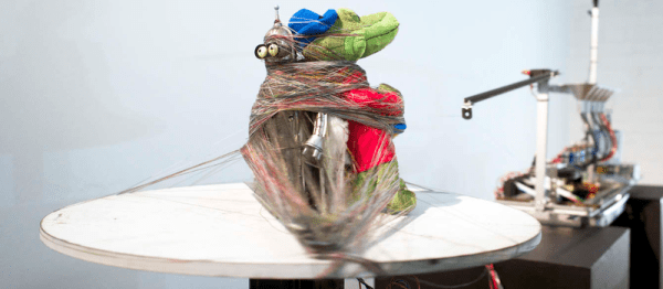
Teleknitting, the brainchild of Moscow artist [vtol], is an interesting project. On one hand, it doesn’t knit anything that is useful in a traditional sense, but on the other, it attempts the complex task of deconstructing broadcasted media into a simpler form of information transmission.
Teleknitting’s three main components are the processing and display block — made up of the antenna, Android tablet, and speaker — the dyeing machine with its ink, sponges, actuators, and Arduino Uno, and the rotating platform for the sacrificial object. A program running on the tablet analyzes the received signal and — as displayed on its screen — gradually halves the number of pixels in the image until there is only one left with a basic representation of the picture’s colour. From there, thread passes over five sponges which dye it the appropriate colour, with an armature that responds to the broadcast’s volume directing where the thread will bind the object.
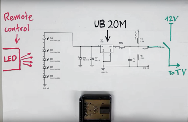
How much effort do you put into conserving energy throughout your daily routine? Diligence in keeping lights and appliances turned off are great steps, but those selfsame appliances likely still draw power when not in use. Seeing the potential to reduce energy wasted by TVs in standby mode, the [Electrical Energy Management Lab] team out of the University of Bristol have designed a television that uses no power in standby mode.
The feat is accomplished through the use of a chip designed to activate at currents as low as 20 picoamps. It, and a series of five photodiodes, is mounted in a receiver which attaches to the TV. The receiver picks up the slight infrared pulse from the remote, inducing a slight current in the receiving photodiodes, providing enough power to the chip which in turn flips the switch to turn on the TV. A filter prevents ambient light from activating the receiver, and while the display appears to take a few seconds longer to turn on than an unmodified TV, that seems a fair trade off if you aren’t turning it on and off every few minutes.
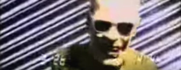
Those of you with long memories and a compulsive TV viewing habit might remember [Max Headroom], a quirky piece of TV ephemera from the late 1980s and early 1990s. [Max] was a supposedly computer generated TV show host and VJ with a pseudomechanical stutter, a slightly blocky rendered head, and a moving background of rendered lines. He looks a little quaint for viewers with a few decades viewing experience of CGI, but in his day he was cutting-edge cypberpunk TV.
The real [Max Headroom] (Fair use) Via Wikimedia Commons.If you were a bored British teenager and future Hackaday writer vegging out in front of your parents’ TV on an April night in 1985, you’d have caught [Max]’s genesis. He strung upon us by rising out of a title screen full of static in the Channel 4 TV movie [Max Headroom]: 20 Minutes into the Future.
The plot is a trip in itself. An investigative journalist seeking to uncover the sinister owners of his network (they run speeded-up adverts with the unfortunate side-effect of causing overweight viewers to explode) is pursued, causing a road accident in which he is injured by a collision with a safety barrier. Hence the name: [Max Headroom]. The network try to cover it up by producing a computerized facsimilie of the reporter which turns out to be an embarassing failure. They scrap the computer and it falls into the hands of a pirate TV station operating from a decrepit campervan, the Alphabetti-eating proprietor of which turns the character it contains into a TV sensation. Meanwhile the reporter escapes, recovers, and prevails over the villains.
The [Max] character proved to be something of a hit, with a TV spin-off series, VJing, adverts, and more. But that wasn’t the whole story of his appearances, back to that unexplained hack of Chicagoland TV.
The Chicago fake [Max Headroom].On the night of the 22nd of November 1987, viewers of WGN were watching a sports program when the screen went blank and they were treated to a few seconds of a slightly home-made [Max Headroom] dancing in front of those trademark moving lines. A couple of hours later on WTTW a rerun of a [Doctor Who] episode was again interrupted with the same fake [Max], this time speaking for a while before, if his performance wasn’t already bizarre enough, being spanked by a woman whose face is off camera.
As a piece of television history it’s an intriguing mystery, though since so little is known about the mechanism through which it was achieved it hasn’t achieved the notoriety in the technical world that you might expect. The stations involved conducted full investigations at the time and failed to locate a culprit, perhaps they should have been looking for that old campervan with the antennae on its roof.
It is very unlikely that a similar stunt could be performed today, with entirely digital TV studios and easy access to encryption technologies for external links to transmitter sites. But in the 1980s a studio would still have been an analogue affair so there would have been more opportunities to insert an unauthorized feed. Next year sees the 30th anniversary of the event, it would be fascinating if the perpetrator would mark it by anonymously revealing how it was achieved. Of course, we’d love to hear how you would have done it in the comments below. Surely we have readers who are intimately familiar with the television broadcasting equipment of the time.
Below the break we’re showing you both fake [Max] intrusions into the Chicago airwaves. First is the short outing on EGN, below that the longer one on WTTV.
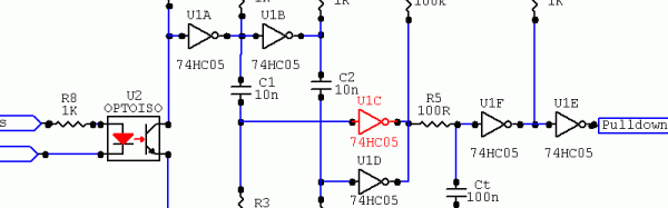
[Newbrain] had a small problem. He’d turn off the TV, but would leave the sound system turned on. Admittedly, not a big problem, but an annoyance, none the less. He realized the TV had a USB port that went off when it did, so he decided to build something that would sense when the USB port died and fake a button press into the amplifier.
He posted a few ideas online and, honestly, the discussion was at least as interesting as the final project. The common thread was to use an optoisolator to sense the 5 V from the USB port. After that, everyone considered a variety of ICs and discretes and even did some Spice modeling.
In the end, though, [Newbrain] took the easy way out. An ATtiny 84 is probably overkill, but it easy enough to press into service. With only three other components, he built the whole thing into a narrow 24-pin socket and taped it to the back of the audio unit’s wired remote control.
Young electronics hackers today are very fortunate to grow up in an era with both a plethora of capable devices to stimulate their imagination, and cheap and ready access to them. Less than the price of a hamburger meal can secure you a Linux computing platform such as the Raspberry Pi Zero, and a huge choice of sensors and peripherals are only an overnight postage envelope away.
Casing back a few decades to the 1980s, things were a little different for electronically inclined youth. We had the first generation of 8-bit microcomputers but they were expensive, and unless you had well-heeled parents prepared to buy you a top-end model they could be challenging to interface to. Other electronic parts were far more expensive, and mail order could take weeks to deliver the goods.
For some of us, this was not a problem. We simply cast around for other sources of parts, and one of the most convenient was the scrap CRT TV you’d find in nearly every dumpster in those days before electronic recycling. If you could make it from 1970s-era consumer-grade discrete components, we probably did so having carefully pored over a heap of large PCBs to seek out the right component values. Good training, you certainly end up knowing resistor colour codes by sight that way.
In the 1980s, Poland was under the grip of martial law as the Communist government of General Wojciech Jaruzelski attempted to repress the independent Solidarity trade union. In Western Europe our TV screens featured as much coverage of the events as could be gleaned through the Iron Curtain, but Polish state TV remained oblivious and restricted itself to wholesome Communist fare.
In September 1985, TV viewers in the city of Toruń sat down to watch an action adventure film and were treated to an unexpected bonus: the screen had a brief overlay with the messages “Solidarity Toruń: Boycotting the election is our duty,” and “Solidarity Toruń: Enough price hikes, lies, repression”. Sadly for the perpetrators, they were caught by the authorities after their second transmission a few days later when they repeated the performance over the evening news bulletin, and they were jailed for four months.
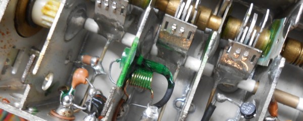
The transmission had been made by a group of dissident radio astronomers and scientists who had successfully developed a video transmitter that could synchronise itself with the official broadcast to produce an overlay that would be visible on every set within its limited transmission radius. This was a significant achievement using 1980s technology in a state in which electronic components were hard to come by. Our description comes via [Maciej Cegłowski], who was able to track down one of the people involved in building the transmitter and received an in-depth description of it.
Transmission equipment seized by the Polish police.
The synchronisation came courtesy of the international effort at the time on Very Long Baseline Interferometry, in which multiple radio telescopes across the world are combined to achieve the effect of a single much larger instrument. Before GPS made available a constant timing signal the different groups participating in the experiment had used the sync pulses of TV transmitters to stay in time, establishing a network that spanned the political divide of the Iron Curtain. This expertise allowed them to create their transmitter capable of overlaying the official broadcasts. The police file on the event shows some of their equipment, including a Sinclair ZX Spectrum home computer from the West that was presumably used to generate the graphics.
There is no surviving recording of the overlay transmission, however a reconstruction has been put on YouTube that you can see below the break, complete with very period Communist TV footage.
![The real [Max Headroom] (Fair use) Via Wikimedia commons.](https://hackaday.com/wp-content/uploads/2016/11/maxheadroommpegman.jpg)
![The Chicago fake [Max Headroom].](https://hackaday.com/wp-content/uploads/2016/11/fake-max.jpg)