If you are going to do something as a joke, there is nothing to say that you can’t do a nice job of it. If you’re like [Michael], a whimsical statement like “Wouldn’t it be funny to put Gründerzeit-style doors on the server cabinet?” might lead down a slippery slope. True to his word, [Michael] not only installed the promised doors, but he did a darn nice job of it.
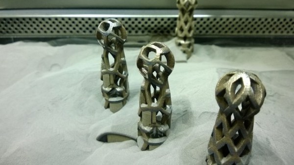
Buying new doors was the easy part because the door frame and hinges were not standardized back then, so there was nothing on the server cabinet to his mount doors. He walks us through all the steps but the most interesting point was the 3D printed door hinges which [Michael] modeled himself and printed in steel. His new hinges feature his personal flair, with some Voronoi patterning while matching the shape of the originals. We love seeing 3D printed parts used as functional hardware, and hinges are certainly a piece of hardware meant to hold up under pressure.
This is not the first 3D printed door hardware we’ve seen. Check out this innovative latch printed as a single piece and here’s the skinny on making flexible objects yourself.