This DIY UPDI Programmer Is Nice And Cheap

[Daumemo] likes experimenting with DIY electronics, and like many people, eventually ran across an AVR microcontroller with a Unified Program and Debug Interface (UPDI). One option is of course to purchase an UPDI programmer, but an even better solution was to make a DIY USB version from nice, cheap parts.

Programming an Attiny404 over the UPDI interface.

UPDI is an interface for external programming and on-chip debugging of microcontrollers, and [Daumemo]’s solution is based on the jtag2updi project. It combines an Arduino Nano (in this case, a clone) with a single resistor, a single capacitor, and a six pin angled header (with a cleverly bent pin) to enable programming UPDI devices over a USB connection. [Daumemo] is happy to report that the device works just fine in both Microchip Studio with AVRDUDE, or PlatformIO.

Is an Arduino Nano a bit overpowered in this role? Maybe, but the price is certainly right. There’s no need for a custom PCB either, since everything can be soldered direct to the Nano board. A matching 3D printed enclosure is about all that’s needed to make a robust and reliable DIY USB UPDI programmer out of a handful of parts, and that sounds good to us.

On the other hand, if you do find yourself making custom PCBs, you may be interested in another of [Daumemo]’s DIY projects: a printable structure to turn a rotary tool into a PCB drill press.

Custom Macro Keyboard With Sweet Backlighting

From the smallest 60% keyboards for those with no desk space to keyboards with number pads for those doing data entry all day, there’s a keyboard size and shape for just about everyone. The only problem, even with the largest keyboards, is that they’re still fairly limited in what they can do. If you find yourself wishing for even more functionality, you might want to build something like this custom macro keyboard with built-in LED backlighting.

Rather than go with a standard mechanical keyboard switch like a Cherry MX, this build is based around TS26-2 pushbuttons with built-in LED lighting. [atkaper] only really needed one button for managing the mute button on MS Teams, but still built a total of eight switches into this keyboard which can all be individually programmed with different functions. The controller is an Arduino Leonardo and the enclosure was 3D printed.

Paired with the classic IBM Model M keyboard, this new macro keyboard adds plenty of functionality while also having control over LED backlighting. Macro keyboards are incredibly useful, especially with their ability to easily change function with control over the software that runs on them. The key to most builds is the 32U4 chip found in some Atmel microcontrollers which allows it to easily pass keyboard (and mouse) functionality to any computer its plugged in to.

Is Your Device Actually USB 3.0, Or Is The Connector Just Blue?

Discount (or even grey market) electronics can be economical ways to get a job done, but one usually pays in other ways. [Majenko] ran into this when a need to capture some HDMI video output ended up with rather less than was expected.

Faced with two similar choices of discount HDMI capture device, [Majenko] opted for the fancier-looking USB 3.0 version over the cheaper USB 2.0 version, reasoning that the higher bandwidth available to a USB 3.0 version would avoiding the kind of compression necessary to shove high resolution HDMI video over a more limited USB 2.0 connection.

The device worked fine, but [Majenko] quickly noticed compression artifacts, and interrogating the “USB 3.0” device with lsusb -t revealed it was not running at the expected speeds. A peek at the connector itself revealed a sad truth: the device wasn’t USB 3.0 at all — it didn’t even have the right number of pins!

A normal USB 3.0 connector is blue inside, and has both sets of pins for backward compatibility (five in the rear, four in the front) like the one shown here.

A USB 3.0 connection requires five conductors, and the connectors are blue in color. Backward compatibility is typically provided by including four additional conductors, as shown in the image here. The connector on [Majenko]’s “USB 3.0” HDMI capture device clearly shows it is not USB 3.0, it’s just colored blue.

Most of us are willing to deal with the occasional glitch or dud in exchange for low prices, but when something isn’t (and never could be) what it is sold as, that’s something else. [Majenko] certainly knows that as well as anyone, having picked apart a defective power bank module to uncover a pretty serious flaw.

Tube Tumbler Provides The Perfect Culture

We’ve all had to shake jars of nail polish, model paint, or cell cultures. Mixing paint is easy – but bacteria and cells need to be agitated for hours.  Happily, laboratory tube tumblers automate this for us. The swishing action is handled with rotation. The vials are mounted at angles around a wheel. The angular offset means the tubes are inclined as they rise, and declined as they fall. This causes the liquid in the tube to slosh from one side to the other as the wheel rotates.  [Sebastian S. Cocioba] aka [ATinyGreenCell] released his plans through Tinkercad and GitHub, and with a name like Sir Tumbalot, we know he must be cultured indeed.

Grab your monocles. Version 2 features a driven wheel lined with magnets to attach tube adapters, and he’s modeled 50mL and twin 15mL tube holders. The attachment points look like a simple beveled rectangle with a magnet pocket, so if you’re feeling vigorous for vials, you can whip up custom sockets and tumble any darn thing. A Trinamic StealthChop chip on a custom PCB controls the pancake stepper, and the whole shebang should cost less than $50USD. We’re wondering what other purposes this modular design could have, like the smallest rock tumbler or resin print rinser.

Making lab equipment is phenomenal for saving money for things that just spin up to a biotech lab.

Continue reading “Tube Tumbler Provides The Perfect Culture”

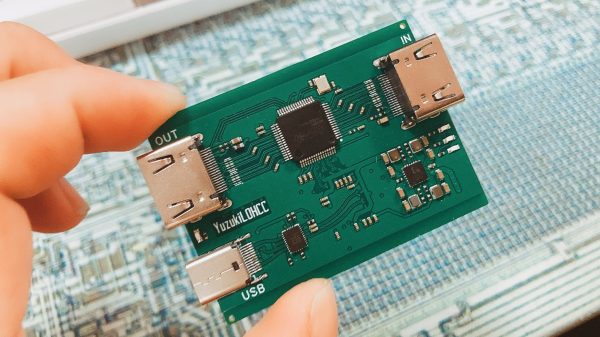
Top side of the VL670 breakout board, with two USB connectors and the VL670 chip in the center.

A Chip To Bridge The USB 2 – USB 3 Divide

On Twitter, [whitequark] has  found and highlighted an intriguing design – a breakout board for the VL670, accompanied by an extensive yet very easy to digest write-up about its usefulness and inner workings. The VL670 is a chip that addresses a surprising problem – converting USB 2.0 signals into USB 3.0.

If you have a USB 2.0 device and a host with only USB 3.0 signals available, this chip is for you. It might be puzzling – why is this even needed? It’s about the little-known dark secret of USB3, that anyone can deduce if they ever have to deal with a 9-pin USB 3.0 connector where one of the three differential pairs doesn’t quite make contact.

When you see a blue “3.0” port, it’s actually USB 2 and USB 3 — two separate interfaces joined into a single connector. USB 3 uses two single-directional differential pairs, akin to PCI-E, whereas USB 2 uses a single bidirectional one, and the two interfaces on a blue connector operate basically independently of each other. There’s many implications to this that are counterintuitive if you simply take “USB 3.0” for “faster backwards-compatible USB”, and they have painful consequences.

For instance, USB 3 hub ICs have two separate hub entities inside – one for USB 3 and one for USB 2. Even if you have a USB 3 hub plugged into a USB 3 port, multiple USB 2 devices plugged into it still cannot break through the USB 2 uplink limit of 480 MBps. If you ever thought that a faster hub with a faster uplink would fix your USB 2 device speed problems – USB-IF engineers, apparently, thought differently; and you might have to find a workaround for your “many cheap SDRs and Pi 4 in a box” setup. Continue reading “A Chip To Bridge The USB 2 – USB 3 Divide”

USB Temperature Logger With Some Extra Tricks

Many of us electronics hacker types tend to have at least the same common equipment on our benches, namely a multimeter, an oscilloscope, some sort of adjustable power supply, and maybe a logic analyzer. These are great tools covering many bases, but dealing with temperature measurements is often neglected. A sudden need for such often results in just buying a either dedicated measurement unit, or some cheap eBay thermocouple board and just rolling with a few hacks. [Jana Marie Hemsing] had a need for measuring the thermal side of things, and got fed up with hacking with piles of boards, and designed herself a proper instrument for the task.

The result is a very tidy four-channel thermocouple frontend, feeding the data into the host computer via USB. Each of the four channels can either be a K-type input or a NTC thermistor input, decided at board assembly time, but you could just build two units with four channels of each and cover all bases. The K-type thermocouple input is based around the MAX31855 series device. While the ‘KASA’ suffixed device is probably most common, if you need to dedicate some channels to handling one of the other six or so other common thermocouple types, that just needs the appropriate MAX31855 variant dropping in, and you’re good to go.

For the controller, [Jana] has chosen the common STM32F0x microcontroller, which handles all the USB protocol side of things. The extra functionality added allows direct driving of a heater controller via the DRV8837 H-Bridge, with a extra few open collector outputs for other things you might want to drive. This allows the logger to function as a kind-of thermal IO device. Firmware is written in good old fashioned STM32 HAL, using the standard STM32CubeMX and the GCC toolchain. It looks like the Makefile came via the STM32 Project Generator route. The firmware has a neat trick up its sleeve too; with a flick of the switch on the back, the firmware can switch between outputting CSV data over a standard USB CDC link (a virtual serial port), or it can present a SCPI terminal interface, enabling integration into existing SCPI-based test flows. Nice work!

We’ve seen a few logging projects on these fair pages, like this battery powered ESP32 logger device. If IoT logging is more your thing, here you go.

A Gameport Joystick To USB-MIDI Converter

These days, live music performance often involves electronic synthesizers and computers rather than traditional instruments played by hand. To aid in his own performances, [alekappa] built a special interface to take signals from a joystick and convert them to MIDI messages carried over USB.

The build is simple and straightforward, using a Teensy LC to interface with a simple gameport joystick. With a smattering of simple components, it’s easy to read the outputs of the joystick with only a little debounce code needed to ensure the joystick’s buttons are read accurately. Similarly, analog axes are read using the analog-to-digital converters onboard the microcontroller.

This data is then converted into control changes, note triggers and velocity levels and sent out over the Teensy LC’s USB interface. A mode switch enables changes to the system’s behaviour to be quickly made. The device is wrapped up in a convenient housing nabbed from an old Gameport-to-USB converter from many years ago.

It’s a neat project and we’re sure the joystick allows [alekappa] to add a new dimension to his performances on stage. We’ve seen other great MIDI controllers, too, from the knitted keyboard to the impressive Harmonicade. If you’ve got your own mad musical build under construction, don’t hesitate to drop us a line!