Apple Never Gave Them USB. Now, They’re Getting It For Themselves

These days we use USB as a default for everything from low-speed serial ports to high-capacity storage, and the ubiquitous connector has evolved into a truly multi-purpose interface. It’s difficult to believe then, that the first Apple Mac to be designed with a USB interface was shipped without it; but that’s the case with 1997’s grey Power Mac G3.

On the personality board are all the footprints for a single USB 1.1 port, but USB-hungry Apple fanboys had to wait for the translucent iMac and later G3 before they had a machine with the parts fitted. [Croissantking] is righting that particular wrong, by piecing together the missing Apple circuit using parts from contemporary cards for PCs. Over a long forum thread there are a few teething problems, but it certainly seems as though grey G3 owners will soon be able to have reliable USB upgrades.

If omitting USB from a 1997 Mac seems unexpected, it’s as well to remember how slow the first USB versions were. At the time SCSI was king in the high-speed peripheral world, and USB seemed more appropriate as a replacement for Apple Desktop Bus and the serial port. Even when they embraced USB they were reluctant to follow the standards of the PC world, as we remember finding out when for curiosity’s sake we tried swapping the mice and keyboards between an iMac and a Windows PC. We have USB’s success to thank for releasing Mac users from a world of hugely overpriced proprietary peripherals.

If you fancy hacking a ’90s PowerMac, make sure you get one that works.

Thanks [Doug] for the tip.

This Week In Security: USB Boom! Acropalypse, And A Bitcoin Heist

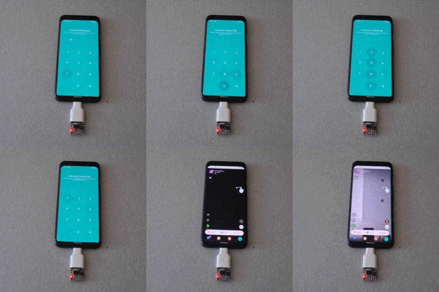
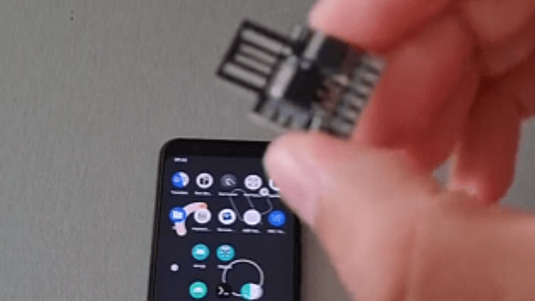
We’ve covered a lot of sketchy USB devices over the years. And surely you know by now, if you find a USB drive, don’t plug it in to your computer. There’s more that could go wrong than just a malicious executable. We’ve covered creative and destructive ideas here on Hackaday, from creative firmware to capacitors that fry a machine when plugged in. But what happened to a handful of Ecuadorian journalists was quite the surprise. These drives went out with a bang.

That is, they literally exploded. The drives each reportedly contained a pellet of RDX, a popular explosive in use by militaries since the second World War. There have been five of these hyperactive USB devices located so far, and only one actually detonated. It seems that one only managed to trigger half of its RDX payload. Because of this, and the small overall size of a USB drive, the explosion was more comparable to a firecracker than a bomb. Continue reading “This Week In Security: USB Boom! Acropalypse, And A Bitcoin Heist”

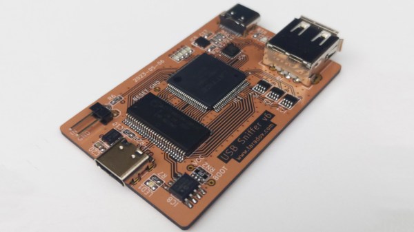
The USB Protocol, Explained

If you can explain what a USB PID, a J state, a K state, and an SOF are, you can probably stop reading now. But if you don’t know or you want a refresher, you can spend 15 minutes watching [Sine Lab’s] straightforward explanation of the USB protocol details. You can find the video below.

The motivation for this is he wants to add USB to his projects using an ATMega with a hardware USB implementation. Honestly, most of the time, you’ll just consume some premade library and get it working that way. However, understanding the terminology can help you, especially if things don’t go as planned.

Continue reading “The USB Protocol, Explained”

A Hackaday.io page screenshot, showing all the numerous CH552 projects from [Stefan].

All The USB You Can Do With A CH552

Recently, you might have noticed a flurry of CH552 projects on Hackaday.io – all of them with professionally taken photos of neatly assembled PCBs, typically with a USB connector or two. You might also have noticed that they’re all built by one person, [Stefan “wagiminator” Wagner], who is a prolific hacker – his Hackaday.io page lists over a hundred projects, most of them proudly marked “Completed”. Today, with all these CH552 mentions in the Hackaday.io’s “Newest” category, we’ve decided to take a peek.

The CH552 is an 8-bit MCU with a USB peripheral, with a CH554 sibling that supports USB host, and [Stefan] seriously puts this microcontroller to the test. There’s a nRF24L01+ transceiver turned USB dongle, a rotary encoder peripheral with a 3D-printed case and knob, a mouse wiggler, an interface for our beloved I2C OLED displays, a general-purpose CH55x devboard, and a flurry of AVR programmers – regular AVRISP, an ISP+UPDI programmer, and a UPDI programmer with HV support. Plus, if USB host is your interest, there’s a CH554 USB host development board specifically. Every single one of these is open-source, with PCBs designed in EasyEDA, the firmware already written (!) and available on GitHub, and a lovingly crafted documentation page for each.

[Stefan]’s seriously put the CH552 to the test, and given that all of these projects got firmware, having these projects as examples is a serious incentive for more hackers to try these chips out, especially considering that the CH552 and CH554 go for about 50 cents a piece at websites like LCSC, and mostly in friendly packages. We did cover these two chips back in 2018, together with a programming guide, and we’ve seen things like badges built with its help, but having all these devices to follow is a step up in availability – plus, it’s undeniable that all the widgets built are quite useful by themselves!

Hobnobbing With The Knob

The scroll wheel might be the best thing that happened to the computer mouse since, well, the computer mouse. But sometimes you want something a little more tangible. For example, with a software-defined radio setup, it doesn’t feel right to scroll your mouse to change frequencies. That’s where [Wagiminator]’ USB knob would come in handy. Marrying a 3D printed case, some addressable LEDs, a rotary encoder, and a CH552E microcontroller, the knob appears to the host operating system as a normal USB keyboard. That means most programs can use it without any special drivers or software.

There’s honestly not much to the hardware. A custom PCB holds two WS2812’s, the tiny CPU, the encoder, and the USB plug. There are a few random discrete components, too, but not many. Everything you need is on the project page. The PCB layout, the software, the schematics, and the 3D print files. The code that does the main work is extremely simple. The USB code is a bit more complex (look in the include directory) but honestly, it isn’t as bad as most USB examples we’ve seen.

This project is ripe for hacking. The software is simple enough to modify easily. The 3D printed case wouldn’t be hard to spruce up or print in different colors. Following the example, this would make a reasonable core for a custom keyboard peripheral that used exotic keys instead of a rotary encoder.

Knobs can be simple or complex. If you want our take on the odd volume control, we used sonar.

DIY Macro Keyboard Wood Be Nice

Editing video tends to involve a lot of keyboard shortcuts, and while this might be fine for the occasional edit, those who regularly deal with video often reach for a macro pad to streamline their workflow. There are plenty of macro keyboards available specifically meant to meet the needs of those who edit a lot of video, but if you want something tailored for your personal workflow you may want to design your own keyboard like this wooden macro pad from [SS4H].

The keyboard itself is built around an STM32 microcontroller, which gives it plenty of power to drive and read the keyboard matrix. It also handles an encoder that is typically included on macro keyboards for video editing, but rather than using a potentiometer-type encoder this one uses a magnetic rotary encoder for accuracy and reliability. There’s a display built into the keyboard as well with its own on-board microcontroller that needs to be programmed separately, but with everything assembled it looks like a professional offering.

[SS4H] built a prototype using 3D printed parts, but for the final version he created one with a wooden case and laser etched keys to add a bit of uniqueness to the build. He also open-sourced all of the PCB schematics and other files needed to recreate this build so anyone can make it if they’d like. It’s not the only macro keyboard we’ve seen before, either, so if you’re looking for something even more esoteric take a look at this keyboard designed to be operated by foot.

Continue reading “DIY Macro Keyboard Wood Be Nice”

All About USB-C: Resistors And Emarkers

If you’ve been following along our USB-C saga, you know that the CC wire in the USB-C cables is used for communications and polarity detection. However, what’s not as widely known is that there are two protocols used in USB-C for communications – an analog one and a digital one. Today, let’s look at the analog signalling used in USB-C – in part, learn more about the fabled 5.1 kΩ resistors and how they work. We’ll also learn about emarkers and the mysterious entity that is VCONN!

USB-C power supply expects to sense a certain value pulldown on the CC line before it provides 5 V on VBUS, and any higher voltages have to be negotiated digitally. The PSU, be it your laptop’s port or a charger, can detect the pulldown (known as Rd) because it keeps a pullup (known as Rp) on the CC line – it then checks if a voltage divider has formed on CC, and whether the resulting voltage is within acceptable range.

If you plug a device that doesn’t make a pulldown accessible through the CC wire in the cable, your device will never get power from a USB-C port, and would only work with a USB-A to USB-C cable. Even the smarter devices that can talk the digital part of USB-C are expected to have pulldowns, it’s just that those pulldowns are internal to the USB-C communication IC used. A USB-C port that wants to receive power needs to have a pulldown.

This part is well-known by now, but we’ve seen lack-of-resistor failures in cheap devices aplenty, and the colloquial advice is “add 5.1 kΩ resistors”. You might be afraid to think it’s so simple, but you’d be surprised. Continue reading “All About USB-C: Resistors And Emarkers”