[Pinkman] creates a smart RGB table lamp based off of the “Odradek device” robot arm from the video game “Death Stranding”.
[Pinkman] adds a XIAO BLE nRF52840 Sense device, with Bluetooth support, microphone and TinyML capability. The nRF52840 is used to push data to the five WS2812 strips, one for each “blade” of the lamp, and also connects to a TTP223 capacitive touch controller to add touch input detection. The TinyML portion of the nRF52840 allows for custom keyword training to turn on the lamp with voice commands ([Pinkman] uses “Bling Bling”). [Pinkman] has also provided Bluetooth control, allowing the color and pattern to be changed from a phone application.
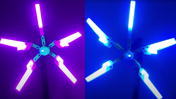
The lamp is 3D printed with the build being based off of [Nils Kal]’s Printables files. Each of the five blades has a white 3D-printed diffusor plate to help ease out the hot spots for the LED strip. The lamp is fully adjustable in addition to having cavities, channels and access points for “invisible” wiring. [Pinkman] has also upgraded the original 3D files to allow for the three wires needed to drive the WS2812, instead of the two wires that [Nils] had allotted in the original.
[Pinkman] has all of the code, STL files and training data available for download, so be sure to check it out. Lamps are a favorite of ours and we’ve featured our fair share, including 3D printed Shoji lamps and RGB wall lamps.
Video after the break!
Continue reading “Illuminate Your Benched Things With This Death Stranding Lamp”