
You normally think of fiber optic as something used in network cables. However, scientists employ dedicated fibers to detect earthquakes. In simple terms, they fire a laser down the fiber and watch reflections caused by imperfections. When vibrations hit the cable, it changes the defects, which show up in the return pattern. However, with the right techniques, those vibrations could just as easily be from people speaking near the cable.
If you are alarmed, there’s good news and bad news. The good news is that the technique seems to be limited to coils of fiber that are not buried, and you have to be within about 5 meters of the fiber. The bad news is that there is plenty of dark cable all over the place. Besides, if researchers can do this successfully, you would imagine three-letter agencies around the world could do it even better.
Continue reading “The Walls Don’t Have Ears, But Fiber Optic Does”


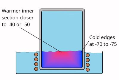 Although the term ‘dry ice’ is generally used for solid CO2, it’s much more accurate to call this ‘dry snow’, as, rather than being actual solid blocks, they are effectively snow that’s been compressed really tightly. While not really necessary for most applications of dry ice, it is possible to make blocks of actual CO2 ice, and thus [Hyperspace Pirate], as someone with a healthy obsession with cold things


