A Pi Pico Oscilloscope

At the budget end of the oscilloscope range lie the so-called pocket ‘scopes. About the size of a deck of cards, they combine a microcontroller and an LCD screen to make an instrument with a bandwidth in the tens of kilohertz and a not-too-sparkling performance. They’re something of a toy, but then again, if all that’s needed is a simple ‘scope for audio frequencies, they make a passable choice in a small package. Now [jgpeiro] has made one which is light years ahead of the toy kits, using a Raspberry Pi Pico, a 100 MHz ADC, and an effort to design a better input circuit.

At its simplest this could be a straightforward op-amp and ADC circuit feeding the Pico, but instead it has multiple stages carefully designed to offer the full bandwidth, and with gain, offset, and trigger settings being set by a series of DAC chips under software control. This and the decent bandwidth make this a much more viable oscilloscope, and one we’d like to see further developed.

By comparison, we took a look at the best of the competition a few years ago.

Bare-Metal STM32: Adding An Analog Touch With ADCs

An Analogue to Digital Converter (ADC) is at its core a straight-forward device: by measuring an analog voltage within a set range and converting the measured level to a digital value we can use this measurement value in our code. Through the use of embedded ADCs in microcontrollers we can address many essential use cases, ranging from measuring the setting on a potentiometer, to reading an analog output line on sensors, including the MCU’s internal temperature and voltage sensors.

The ADCs found in STM32 MCUs have a resolution between 12 to 16 bits, with the former being the most common type. An ADC can be configured to reduce this resolution, set a specific sampling speed, and set up a multi-mode configuration depending on the exact ADC peripheral. STM32 MCUs feature at least a single ADC peripheral, while some have multiple. In this article we will take a look at how to configure and use the basic features of the ADCs in STM32 MCUs, specifically the ADCs found in F0 and the ADC5_V1_1 type as found in most F3-family MCUs.

Continue reading “Bare-Metal STM32: Adding An Analog Touch With ADCs”

Retrotechtacular: The Forgotten Vacuum Tube A/D Converters Of 1965

In any era, the story of electronics has very much been about figuring out how to make something happen with what’s available at the time. And as is often the case, the most interesting developments come from occasions when needs exceed what’s available. That’s when real innovation takes place, even if circumstances conspire to keep the innovation from ever taking hold in the marketplace.

This gem of a video from the Antique Wireless Association has a perfect example of this: the long-lost analog-to-digital converter vacuum tube. Like almost every mid-20th-century innovation in electronics, this one traces its roots back to the Bell Laboratories, which was keenly interested in improving bandwidth on its massive network of copper lines and microwave links. As early as 1947, one Dr. Frank Gray, a physicist at Bell Labs, had been working on a vacuum tube that could directly convert an analog signal into a digital representation. His solution was a cathode ray tube similar to the CRT in an oscilloscope. A beam of electrons would shine down the length of the tube onto a shadow mask containing holes arranged in a “reflected binary code,” which would later be known as a Gray code. The analog signal to be digitized was applied to a pair of vertical deflector plates, which moved the beam into a position along the plate corresponding to the voltage. A pair of horizontal deflector plates would then scan the beam across the shadow mask; where electrons fell on a hole, they would pass through to an output plate to be registered as a bit to be set.

Continue reading “Retrotechtacular: The Forgotten Vacuum Tube A/D Converters Of 1965”

Processing Audio With The RP2040

The Raspberry Pi, although first intended as an inexpensive single-board computer for use in education, is now ubiquitous in electronics communities. Its low price as well as Linux platform and accessible GPIO make it useful in many places outside the classroom. But, if you want to abandon the ease-of-use in favor of an even lower price, the Raspberry Pi foundation makes that possible as well with the RP2040 chip, commonly found on the Pico. [Jason] shows us one way to make use of this powerful chip by putting one in an audio digital signal processing board.

While development boards are available for this chip, [Jason] has opted instead for a custom PCB which he designed himself and includes an integrated headphone amplifier and 3.5 mm audio jacks. To do the actual DSP work, the RP2040 chip uses three 12-bit ADC channels and 16 controllable PWM channels. The platform is also equipped with the TLV320AIC3254 codec from Texas Instruments. With all of this put together, he has a functioning open-source platform he calls the DS-Pi.

[Jason] has built this as a platform for guitar effects and as a customizable guitar amp modeler, but with a platform that is Arduino-compatible and fairly easy to program it could be put to use for anything involving other types of music or audio processing, like this specialized MIDI-compatible guitar effects platform which is built around the same processor.

Our Favorite Things: Binary Search

You might not think that it would be possible to have a favorite optimization algorithm, but I do. And if you’re well-versed in the mathematical art of hill climbing, you might be surprised that my choice doesn’t even involve taking any derivatives. That’s not to say that I don’t love Newton’s method, because I do, but it’s just not as widely applicable as the good old binary search. And this is definitely a tool you should have in your toolbox, too.

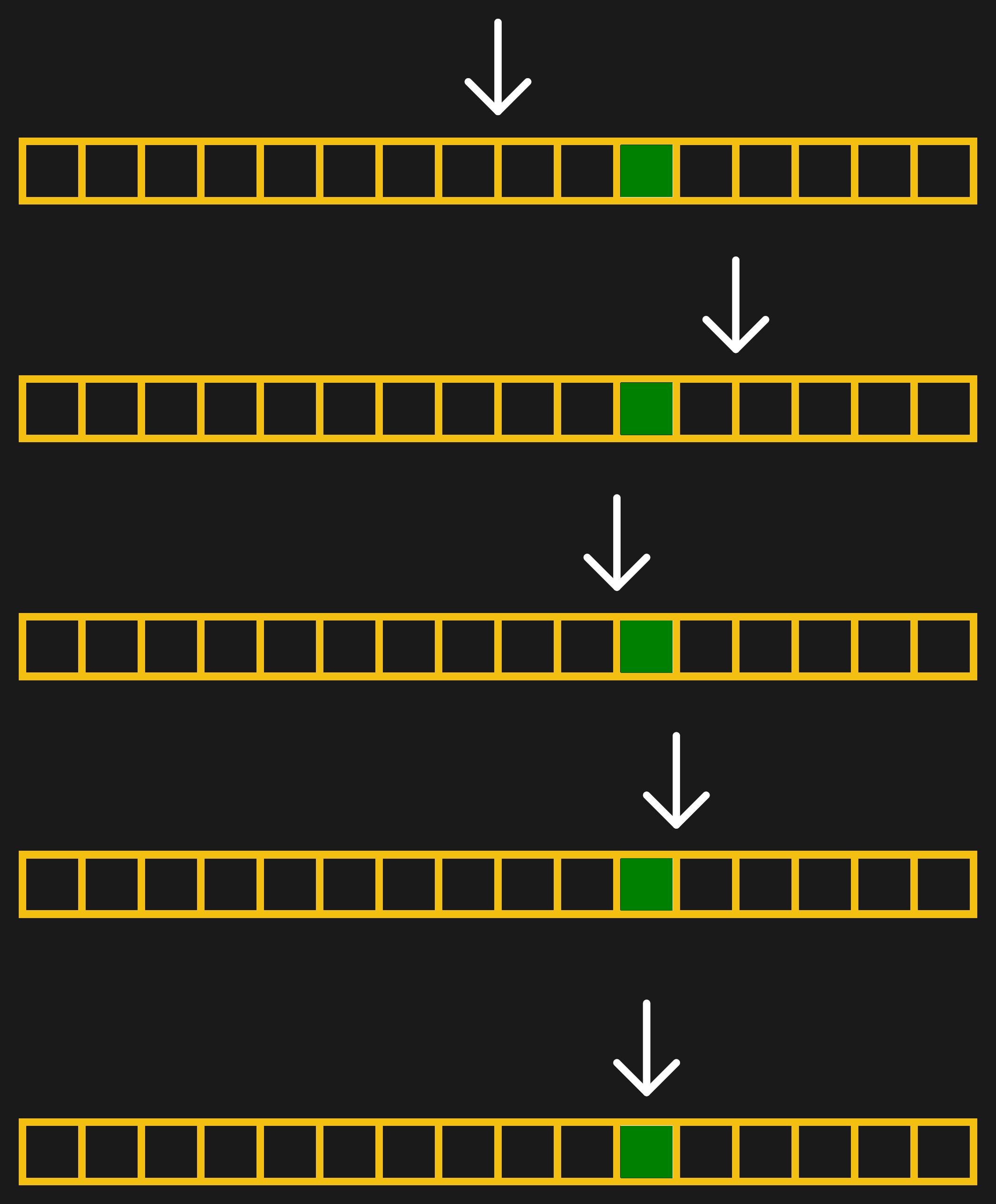
Those of you out there who slept through calculus class probably already have drooping eyelids, so I’ll give you a real-world binary search example. Suppose you’re cropping an image for publication on Hackaday. To find the best width for the particular image, you start off with a crop that’s too thin and one that’s too wide. Start with an initial guess that’s halfway between the edges. If this first guess is too wide, you split the difference again between the current guess and the thinnest width. Updated to this new guess, you split the differences again.

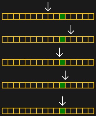
But let’s make this even more concrete: an image that’s 1200 pixels wide. It can’t get wider than 1200 or thinner than 0. So our first guess is 600. That’s too thin, so we guess 900 — halfway between 600 and the upper limit of 1200. That ends up too wide, so we next guess 750, halfway between 600 and 900. A couple more iterations get us to 675, then 638, and then finally 619. In this case, we got down to the pixel level pretty darn fast, and we’re done. In general, you can stop when you’re happy, or have reached any precision goal.

[Ed note: I messed up the math when writing this, which is silly. But also brought out the point that I usually round the 50% mark when doing the math in my head, and as long as you’re close, it’s good enough.]

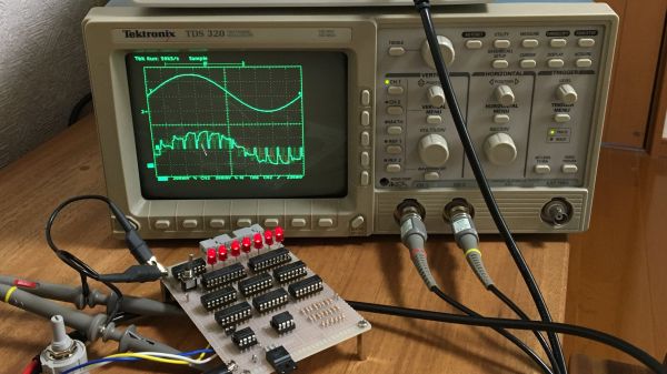
What’s fantastic about binary search is how little it demands of you. Unlike fancier optimization methods, you don’t need any derivatives. Heck, you don’t even really need to evaluate the function any more precisely than “too little, too much”, and that’s really helpful for the kind of Goldilocks-y photograph cropping example above, but it’s also extremely useful in the digital world as well. Comparators make exactly these kinds of decisions in the analog voltage world, and you’ve probably noticed the word “binary” in binary search. But binary search isn’t just useful inside silicon. Continue reading “Our Favorite Things: Binary Search”

Pressure Gauge Built In A Vacuum

Necessity might be the mother of all invention, but we often find that inventions around here are just as often driven by expensive off-the-shelf parts and a lack of willingness to spend top dollar for them. More often than not, we find people building their own tools or parts as if these high prices are a challenge instead of simply shrugging and ordering them from a supplier. The latest in those accepting the challenge of building their own parts is [Advanced Tinkering] who needed a specialty pressure gauge for a vacuum chamber.

In this specific case, the sensor itself is not too highly priced but the controller for it was the deal-breaker, so with a trusty Arduino in hand a custom gauge was fashioned once the sensor was acquired. This one uses an external analog-to-digital converter to interface with the sensor with 16-bit resolution, along with some circuitry to bring the ~8 V output of the sensor down to the 5 V required by the microcontroller. [Advanced Tinkering] wanted a custom live readout as well, so a 3D printed enclosure was built that includes both an LCD readout of the pressure and a screen with a graph of the pressure over time.

For anyone else making sensitive pressure measurements in a vacuum chamber, [Advanced Tinkering] made the project code available on a GitHub page. It’s a great solution to an otherwise overpriced part provided you have the time to build something custom. If you’re looking for something a little less delicate, though, take a look at this no-battery pressure sensor meant to ride along on a bicycle wheel.

Continue reading “Pressure Gauge Built In A Vacuum”

Successive approximation register ADC

Homebrew Circuit Explores The Mysteries Of Analog-to-Digital Conversion

When it comes to getting signals from an analog world into our computers, most of us don’t give much thought to how the hardware that does the job works. But as it turns out, there are a number of ways to skin the analog to digital conversion cat, and building your own homebrew successive approximation register ADC is a great way to dispel some of the mystery.

From his description of the project, it’s clear that [Mitsuru Yamada] wasn’t looking to build a practical ADC, but was more interested in what he could learn by rolling his own. A successive approximation register ADC works by quickly cycling through all possible voltage levels in its input range, eventually zeroing in on the voltage of the input signal at that moment and outputting its digital representation. The video below shows how the SAR ADC works visually, using an oscilloscope to show both the input voltage and the output of the internal R-2R DAC. The ADC has an input range of 0 V to 5 V and seven bits of resolution and uses nothing but commonly available 74xx series logic chips and a couple of easily sourced analogs for the sample-hold and comparator section. And as usual with one of his projects, the build quality and workmanship are impeccable.

We love these sorts of projects, which are undertaken simply for the joy of building something and learning how it works. For more of [Yamada-san]’s projects, check out his 6502-based RPN calculator, or the serial terminal that should have been.

Continue reading “Homebrew Circuit Explores The Mysteries Of Analog-to-Digital Conversion”