Op-Amp Challenge: Light Up Breadboard Shows Us The Signals

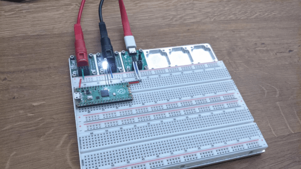
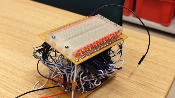
Most Hackaday readers will no doubt at some point used a solderless breadboard for prototyping. They do the job, but sometimes their layout can be inflexible and keeping track of signals can be a pain. There’s a neat idea from [rasmusviil0] which might go some way to making the humble breadboard easier to use, it’s a breadboard in which each line is coupled via an op-amp buffer to an LED. In this way it can be seen at a glance some indication of the DC voltage present.

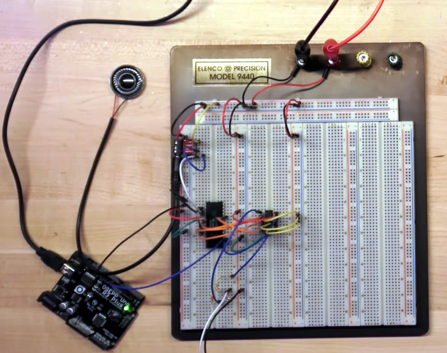
It’s an idea reminiscent of those simple logic probes which were popular years ago, but its implementation is not entirely easy. Each circuit is simple enough, but to replicate it across all the lines in a breadboard makes for a huge amount of quad op-amp chips stuffed onto one piece of stripboard as well as a veritable forest of wires beneath the board.

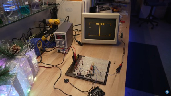
The effect is of a breadboard crossed with a set of blinkenlights, and we could see that for simple digital circuits it could have some utility if not so much for higher frequency or analogue signals. Certainly it’s an experiment worth doing, and indeed it’s not the first tricked out breadboard we’ve seen.

Bust Out That Old Analog Scope For Some Velociraster Fun!

[Oli Wright] is back again with another installation of CRT shenanigans. This time, the target is the humble analog oscilloscope, specifically a Farnell DTV12-14 12 MHz dual-channel unit, which features a handy X-Y mode. The result is the Velociraster, a simple (in hardware terms) Raspberry Pi Pico based display driver.

Using a Pico to drive a pair of AD767 12-bit DACs, the outputs of which drive the two ‘scope input channels directly, this breadboard and pile-of-wires hack can produce some seriously impressive results. On the software side of things, the design is a now a familiar show, with core0 running the application’s high-level processing, and core1 acting in parallel as the rendering engine, determining static DAC codes to be pushed out to the DACs using the DMA and the PIO.

Continue reading “Bust Out That Old Analog Scope For Some Velociraster Fun!”

It’s A 486 Computer, On A Breadboard

Ever since the 1970s, a frequent project has been to take a microprocessor and construct a computer system on a breadboard or stripboard. Usually these machines feature a familiar 8-bit processor such as a 6502 or a Z80 because of their breadboard-friendly DIP packages, but there is surprisingly little reason why some of the more recent silicon can’t be treated in the same way. [FoxTech] is leading the way on this, by making a breadboard computer using an 80486DX.

A 1990-era 32-bit desktop CPU seems unpromising territory for this application, but its architecture is surprisingly accessible. It needs a breakout board to gain access to its various lines, but beyond that it can be interfaced to in a very similar way to those earlier chips.

So far there are two videos in the series, which we’ve placed below the break. The first one introduces the project and shows the basic set-up. A 486 running NOPs may produce a pretty light show, but as he starts to show in the second video, it’s capable of more. The eventual aim is to have a simple but fully functional breadboard computer, so he’s starting with logic to decode the 32-bit bus on the 486 into the 8-bit bus he’s going to use.

It’s fascinating to learn about how the 32-bit 486 handles its interfacing and deals with four bytes at once, and we’re very much looking forward to seeing this project play out. The 486 may be on life support here in 2023, but that doesn’t mean it can’t still receive some love.

Continue reading “It’s A 486 Computer, On A Breadboard”

A man sits in front of a wooden table. There is a black box with a number of knobs hand-labeled on blue painter's tape. A white breadboard with a number of wires protruding from it is visible on the box's left side. An oscilliscope is behind the black box and has a yellow waveform displaying on its screen.

A More Expressive Synth Via Flexure

Synthesizers can make some great music, but sometimes they feel a bit robotic in comparison to their analog counterparts. [Sound Werkshop] built a “minimum viable” expressive synth to overcome this challenge. (YouTube)

Dubbed “The Wiggler,” [Sound Werkshop]’s expressive synth centers on the idea of using a flexure as a means to control vibrato and volume. Side-to-side and vertical movement of the flexure is detected with a pair of linear hall effect sensors that feed into the Daisy Seed microcontroller to modify the patch.

The build itself is a large 3D printed base with room for the flexure and a couple of breadboards for prototyping the circuits. The keys are capacitive touch pads, and everything is currently held in place with hot glue. [Sound Werkshop] goes into detail in the video (below the break) on what the various knobs and switches do with an emphasis on how it was designed for ease of use.

If you want to learn more about flexures, be sure to checkout this Open Source Flexure Construction Kit.

Continue reading “A More Expressive Synth Via Flexure”

Tidy Breadboard Uses Banana Bread

Self-described passionate maker in the electronics and 3D printing world, [Jakob], aka [testudor], was getting frustrated trying to connect banana plugs to solderless breadboards. Project Banana Bread was born — small banana jack adaptors and a companion tray with pockets to hold up to six modules.

The base in the photo is made from 5083 aluminum, machined on a homemade CNC router. But design files for a yet-to-be-tested 3D printer version are available as well. As can happen, he strayed from the original goal of solving the banana jack issue, and also cranked out a USB-serial port and a blank template module for any custom interfaces folks may want to implement.

If it is only power connections you are interested in, we covered the Open Power project back in 2019. And also don’t forget the mother of all breadboards, this 1960s behemoth we wrote about last year. What kinds of breadboard interface modules do you find most useful? Let us know in the comments below.


Resurrecting PONG, One Jumper Wire At A Time

Between 1976 and 1978, over one million Coleco Telstar video game consoles were sold. The Killer App that made them so desirable? PONG. Yep, those two paddles bouncing a ball around a blocky tennis court were all the rage and helped usher in a new era. And as [Dave] of Dave’s Garage shows us in the video below the break, the bringing the old console back to life proved simpler than expected!

Thankfully, the console is built around what [Dave] quite aptly calls “PONG on a chip”, the General Instrument AY-3-8500 which was designed to make mass production of consoles possible. The chip actually contains several games, although PONG was the only one in use on the Coleco.

After removing the CPU from the non-functional console, [Dave] breathed life into it by providing a 2 MHz clock signal that was generated by an Arduino, of all things. A typical 2N2222 amplifies the audio, and a quick power up showed that the chip was working and generating audio.

Video is smartly taken care of just as it was in the original design, by combining various signals with a 4072 OR gate. With various video elements and synchronization patterns combined into a composite video signal, [Dave] was able to see the game on screen, but then realized that he’d need to design some “paddles”. We’ll leave that up to you to watch in the video, but make sure to check the comments section for more information on the design.

Is a breadboarded PONG console not retro enough for you? Then check out this old school mechanical version that was found languishing in a thrift store.

Continue reading “Resurrecting PONG, One Jumper Wire At A Time”

Prototyping The Prototype

For basic prototyping, the go-to tool to piece together a functioning circuit is the breadboard. It’s a great way to prove a concept works before spending money and time on a PCB. For more complex tasks we can make use of simulation software such as SPICE. But there hasn’t really been a tool to blend these two concepts together. That’s what CRUMB is hoping to solve as a tool that allows simulating breadboard circuits.

Currently, most basic circuit functions are working for version 1.0. This includes passive components like resistors, capacitors, switches, some LEDs, and potentiometers, as well as some active components like transistors and diodes. There are some logic chips available such as 74XX series chips and 555 timers, which opens up a vast array of circuit building. There’s even an oscilloscope feature, plus audio output to incorporate buzzers into the circuit simulation. Currently in development is an LCD display module and improvements to the oscilloscope.

Besides prototyping, this could be useful for anyone, students included, who is learning about circuits without the need to purchase any hardware. The major downside to this project is that it there doesn’t seem to have a free or trial version, the source is not available, and it’s only for sale on Steam, Apple Store, and Google Play. That being said, there is a forum available for users to discuss problems and needs for future versions, so it’s possible that a community could build up around it. We’ve seen previously non-free versions of circuit simulation software become more open after some time, so it’s not out of the realm of possibility.

Thanks to [Thomas] for the tip!