An OLED Photo Frame Powered By The ATtiny85

Rolling your own digital picture frame that loads images from an SD card and displays them on an LCD with a modern microcontroller like the ESP32 is an afternoon project, even less if you pull in somebody else’s code. But what if you don’t have the latest and greatest hardware to work with?

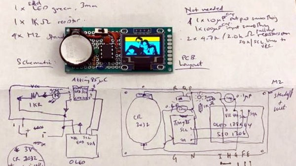
Whether you look at it as a practical application or an interesting experiment in wringing more performance out of low-end hardware, [Assad Ebrahim]’s demonstration of displaying digital photographs on an OLED using the ATtiny85 is well worth a look. The whole thing can put put together on a scrap of perfboard with a handful of common components, and can cycle through the five images stored on the chip’s flash memory for up to 20 hours on a CR2032 coin cell.

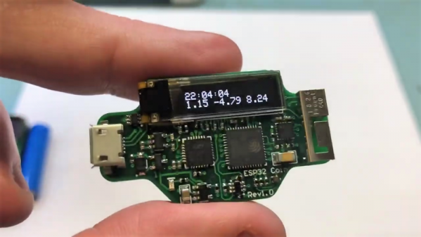
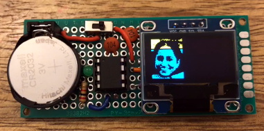
As you might expect, the biggest challenge in this project is getting all the code and data to fit onto the ATtiny85. To that end [Assad] wrote his own minimal driver for the SSD1306 OLED display, as the traditional Adafruit code took up too much space. The driver is a pretty bare bones implementation, but it’s enough to initialize the screen and get it ready for incoming data. His code also handles emulating I2C over Atmel’s Universal Serial Interface (USI) at an acceptable clip, so long as you bump the chip up to 8 MHz.

For the images, [Assad] details the workflow he uses to take the high-resolution color files and turn them into an array of bytes for the display. Part of that it just scaling down and converting to 1-bit color, but there’s also a bit of custom Forth code in the mix that converts the resulting data into the format his code expects.

This isn’t the first time we’ve seen somebody use one of these common OLED displays in conjunction with the ATtiny85, and it’s interesting to see how their techniques compare. It’s not a combination we’d necessarily chose willingly, but sometimes you’ve got to work with whats available.

PixMob LED Wristband Teardown (Plus IR Emitters And How To Spot Them)

PixMob units are wearable LED devices intended for crowds of attendees at events like concerts. These devices allow synchronized LED effects throughout the crowd. [yeokm1] did a teardown of one obtained from a preview for the 2019 Singapore National Day Parade (NDP), and in the process learned about the devices and their infrastructure.

Suspected IR emitter for the PixMob units, mounted on a lighting tower (marked here in white).

PixMob hardware has been known to change over time. This version has two RGB LEDs (an earlier version had only one), an unmarked EEPROM, an unmarked microcontroller (suspected to be the Abov MC81F4104), and an IR receiver module. Two CR1632 coin cells in series power the device. [yeokm1] has made the schematic and other source files available on the teardown’s GitHub repository for anyone interested in a closer look.

One interesting thing that [yeokm1] discovered during the event was the apparent source of the infrared emitter controlling the devices. Knowing what to look for and reasoning that such an emitter would be mounted with a good view of the crowd, [yeokm1] suspected that the IR transmitter was mounted on a lighting tower. Viewing the tower through a smartphone’s camera revealed a purplish glow not visible to the naked eye, which is exactly the way one would expect an IR emitter to look.

Sadly, there wasn’t any opportunity to record or otherwise analyze the IR signals for later analysis but it’s possible that the IR protocol might be made public at some point. After all, running custom code on an earlier PixMob board was made possible in part by asking the right people for help.

Tiny Two-Digit Thermometer Has Long Battery Life

Like most of his work, this tiny two-digit thermometer shows that [David Johnson-Davies] has a knack for projects that make efficient use of hardware. No pin is left unused between the DS18B20 temperature sensor, the surface mount seven-segment LED displays, and the ATtiny84 driving it all. With the temperature flashing every 24 seconds and the unit spending the rest of the time in a deep sleep, a good CR2032 coin cell should power the device for nearly a year. The board itself measures only about an inch square.

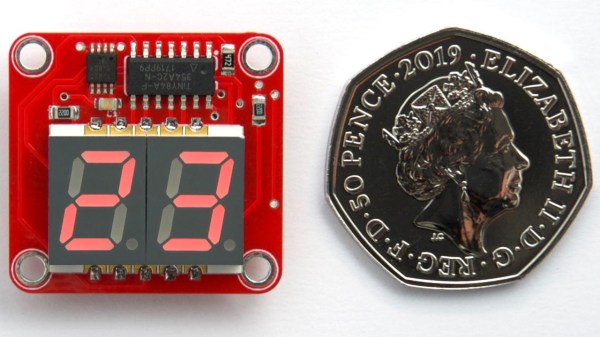
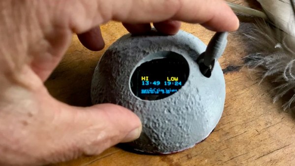
You may think that a display that flashes only once every 24 seconds might be difficult to actually read in practice, and you’d be right. [David] found that it was indeed impractical to watch the display, waiting an unknown amount of time to read some briefly-flashed surprise numbers. To solve this problem, the decimal points flash shortly before the temperature appears. This countdown alerts the viewer to an incoming display, at the cost of a virtually negligible increase to the current consumption.

[David]’s project write-up explains how everything functions. He also steps through the different parts of the source code to explain how everything works, including the low power mode. The GitHub repository holds all the source files, and the board can also be ordered direct from OSH Park via their handy shared projects feature.

Low power consumption adds complexity to projects, but the payoffs can easily be worth the time spent implementing them. We covered a detailed look into low power WiFi microcontrollers that is still relevant, and projects like this weather station demonstrate practical low power design work.

A Coin Cell Powers This Tiny ESP32 Dev Board

Just for the challenge, just for fun, just for bragging rights, and just to do a little showing off – all perfectly valid reasons to take on a project. It seems like one or more of those are behind this tiny ESP32 board that’s barely larger than the coin cell that powers it.

From the video below, [Mike Rankin] has been working down the scale in terms of powering and sizing his ESP32 builds. He recently completed a project with an ESP32 Pico D4 and an OLED display that fits exactly on an AA battery holder, which he populated with a rechargeable 14550. Not satisfied with that form factor, he designed another board, this time barely larger than the LIR2450 rechargeable coin cell in its battery holder. In addition to the Pico D4, the board sports a USB charging and programming socket, a low drop-out (LDO) voltage regulator, an accelerometer, a tiny RGB LED, and a 96×16 OLED display. Rather than claim real estate for switches, [Mike] chose to add a pair of pads to the back of the board and use them as capacitive touch sensors. We found that bit very clever.

Sadly, the board doesn’t do much – yet – but that doesn’t mean we’re not impressed. And [Mike]’s no stranger to miniaturization projects, of course; last year’s Open Hardware Summit badge was his brainchild.

Continue reading “A Coin Cell Powers This Tiny ESP32 Dev Board”

A Better Charger For Your Coin Cell Batteries

Rechargeable coin cell batteries are great for all your small projects. They look exactly like regular coin-cell batteries, but in a shocking turn of events you can recharge these little guys. They can put out a reasonable amount of current, and they’re small. Just what you need for your Arduino smart watch, or whatever else the kids are doing these days.

But if these batteries are rechargeable, you need a charger. That’s where [Jon]’s entry for the Hackaday Prize comes in handy. It’s a small, cheap charger for LIR2032 and other rechargeable batteries comes in. It’s barely larger than the battery itself, and it plugs right into a USB port. How this isn’t a product already, we’ll never know.

The circuit on this coin cell charger is built from an MCP73831, a nice single cell, lithium ion and lithium polymer charge management controller. In the standard, ‘I only need to read the first page of the datasheet’ configuration, this chip can put 500 mA into a battery. Standard rechargeable coin cells only have a capacity of 40 mAh, so you’ve got plenty of headroom at 1C.

The total cost for this project was under $8 for three boards, and a BOM cost of $2 for one. That’s fourteen bucks for three of them, if you know how to solder, compared to a standard, off-the-shelf charger for about $20. Building this is cheaper than buying the equivalent product. It’s unbelievable, but true.

The Tide Is High, And This Clock Lets You Know

In case you happen to have an ocean nearby, you’re probably familiar with its rising and falling tides. And if mudflat hiking is a thing in your area, you’re also aware of the importance of good timing and knowing when the water will be on its way back. Tide clocks will help you to be prepared, and they are a fun alternative to your usual clock projects. If you’re looking for a starting point, [rabbitcreek] put together an Arduino-based tide clock kit for educational purposes.

If you feel like you’re experiencing some déjà vu here, this indeed isn’t [rabbitcreek]’s first tide clock project. But unlike his prior stationary clock, he has now created a small and portable, coin-cell version to take with you out on the sea. And what shape would better fit than a 3D printed moon — unfortunately the current design doesn’t offer much waterproofing.

For the underlying tide calculation itself, [rabbitcreek] uses just like in his previous project [Luke Miller]’s location-based library for the ubiquitous DS1307 and DS3213 real-time clocks. Of course, if you also want to keep track of other events on your clock, why not set up calendar events for the next rising tide?

How Low Can An ESP8266 Go?

We’ve been tuned into coin cell designs lately given the coin cell challenge, so we were interested in [CNLohr]’s latest video about pushing the ESP8266 into the lowest-possible battery drain with coin cells. The result is a series of hacks, based on a reverse-engineered library and depends on a modified router, but that gets the power consumption down by more than a factor of ten!

Although the ESP8266 has a deep sleep mode that draws only 20 microamps or so, that isn’t as rosy as it seems. If you could go to sleep for a while, wake up for just a moment, send your data, and then go back to sleep, that might be one thing. But when you use conventional techniques, the device wakes up and has to do about ten seconds of work (at high power) to connect to a nearby access point. Then it can do what you want and go back to sleep. That ten-second hit is a killer on small batteries.

Since that’s all you can do with the standard libraries, the next step was to find [pvvx] who has reverse engineered a great deal of the libraries and provides a library with no WiFi capability. That’s a two-edged sword. The pro is you get a 30 ms startup from a deep sleep. The downside is — well — you don’t have WiFi.

Continue reading “How Low Can An ESP8266 Go?”