Proximity sensors are common enough in automation projects that we hardly give them a second thought — pick something with specs that match the job and move on. But they can be fussy to get adjusted just right, a job made more difficult if they’re located in some out-of-the-way corner.
But where lies a challenge, there’s also an opportunity, as [Ido Gendel] shows us with this remote-controlled proximity sensor. The story behind this clever little hack starts with an off-the-shelf sensor, the kind with an IR LED and a phototransistor pointed in the same direction that gives a digital output when the light bouncing back into the phototransistor exceeds a certain threshold. It was setting the threshold that gave [Ido]’s client trouble, so [Ido] decided to build a programmable drop-in replacement to make the job easier.
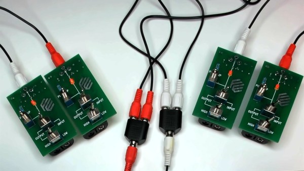
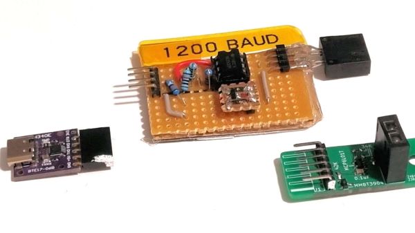
The first try at this used an OBP732 reflective transmitter and an ATtiny202 microcontroller and had three pads on the PCB for programming. This still required physical contact for programming, though, so [Ido] had the idea to use the sensor for wireless IR programming. The microcontroller on version two was switched to an ATtiny212, and a couple of components were added to control the power of the LED so the sensor could do double duty. A programmer using the same sensor and a USB-to-UART adapter completes the system, and allows the sensor threshold to be set just by shining the programmer in its general direction from up to 25 cm away.
We think that getting multiple uses from a single sensor is pretty clever, so hats off for this one. It’s not the first time we’ve featured one of [Ido]’s projects, but it’s been quite a while — this one-clock-cycle-a-day Shabbat clock was the most recent, but you can clearly see the roots of the sensor project in this mouse pointer data encoder that goes all the way back to 2015.