Retrotechtacular: 1950s Televisions Were Beasts

Television has been around for a long time, but what we point to and call a TV these days is a completely different object from what consumers first fell in love with. This video of RCA factory tours from the 1950s drives home how foreign the old designs are to modern eyes.

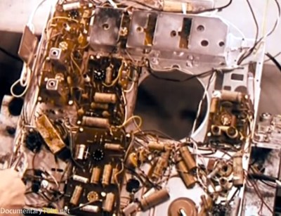
Right from the start the apparent chaos of the circuitry is mindboggling, with some components on circuit boards but many being wired point-to-point. The narrator even makes comments on the “new technique for making electrical connections” that uses a wire wrapping gun. The claim is that this is cleaner, faster, and neater than soldering. ([Bil Herd] might agree.) Not all of the methods are lost in today’s manufacturing though. The hand-stuffing and wave soldering of PCBs is still used on lower-cost goods, and frequently with power supplies (at least the ones where space isn’t at a premium).

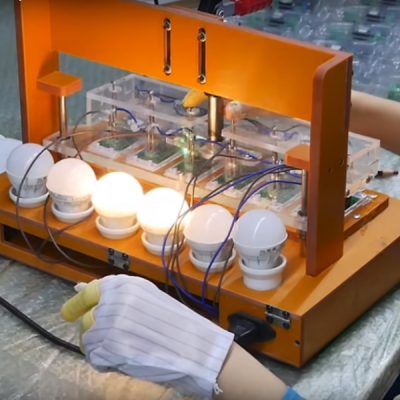
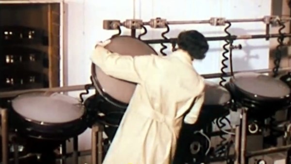
It’s no surprise when talking about 60+ year-old-designs that these were tube televisions. But this goes beyond the Cathode Ray Tube (CRT) that generates the picture. They are using vacuum tubes, and a good portion of the video delves into the manufacture and testing of them. You’ll get a glimpse of this at 3:20, but what you really want to see is the automated testing machine at 4:30. Each tube travels along a specialized conveyor where the testing goes so far as to give a  few automated whacks from corks on the ends of actuators. As the tube gauntlet progresses, we see the “aging” process (around 6:00) when each tube is run at 3-4 times the rated filament voltages. Wild!

There’s a segment detailing the manufacture of the CRT tubes as well, although these color tubes don’t seem to be for the model of TV being followed during the rest of the films. At about 7:07 they call them “Color Kinescopes”, an early name for RCA’s CRT technology.

During the factory tours we get the overwhelming feeling that this manufacturing is more related to automotive than modern electronic. These were the days when televisions (and radios) were more like pieces of furniture, and seeing the hulking chassis transported by hanging conveyors is just one part of it. The enclosure plant is churning out legions of identical wooden consoles. This begins at 11:55 and the automation shown is very similar to what we’d expect to see today. It seems woodworking efficiency was already a solved problem in the ’50s.

Continue reading “Retrotechtacular: 1950s Televisions Were Beasts”

Take The Coin Cell Challenge This Weekend!

The year is drawing to a close, and we have a weekend project for you to while away the remaining hours. Take the Coin Cell Challenge!

The point of the challenge is to do something interesting with a coin cell. That’s it! It’s a challenge that can be as simple or as involved as you want. Low power is where it’s at these days, so if you’ve never used the hardware sleep modes in your favorite microcontroller, that would make an excellent challenge entry. Show us what you’re able to do with short wake periods, and talk about when and why that wake happens. Or go a completely different route and build your own cell!

[Ben Krasnow] makes the most of a tiny power source
The top twenty entries will each receive a $100 Tindie credit so they can score some excellent gear. Three top winners in some special areas who will each be awarded a $500 cash prize. We’re looking for something interesting that demonstrates longest life (Lifetime Award), something that burns through that coin cell as if it’s going out of style (Supernova Award), and something that fills us with disbelief (Heavy Lifting Award) because it shouldn’t be possible with “just a coin cell”.

One of our biggest inspirations for this contest was [Ben Krasnow] who managed to squeeze enough juice out of a miniscule coin cell to power his Flashing Light Prize entry, only because he reduced internal resistance by heating the cell with an air gun (here’s the Hackaday coverage of that project). And [Elliot Williams] wrote a great guide on what kind of juice you can expect to get out of a cell. Take these to heart and do something interesting this weekend. Enter now!

Dig Into The Apple Device Design Guide

Millions of people worldwide have just added new Apple gadgets to their lives thanks to the annual end of December consumerism event. Those who are also Hackaday readers are likely devising cool projects incorporating their new toys. This is a good time to remind everybody that Apple publishes information useful for such endeavors: the Accessory Design Guidelines for Apple Devices (PDF).

This comes to our attention because [Pablo] referenced it to modify an air vent magnet mount. The metal parts of a magnetic mount interferes with wireless charging. [Pablo] looked in Apple’s design guide and found exactly where he needed to cut the metal plate in order to avoid blocking the wireless charging coil of his iPhone 8 Plus. What could have been a tedious reverse-engineering project was greatly simplified by Reading The… Fine… Manual.

Apple has earned its reputation for hacker unfriendliness with nonstandard fasteners and liberal use of glue. And that’s even before we start talking about their digital barriers. But if your project doesn’t involve voiding the warranty, their design guide eliminates tedious dimension measuring so you can focus on the fun parts.

Dimensioned drawing of Apple iPad Pro

This guide is packed full of dimensioned drawings. A cursory review shows that they look pretty good and aren’t terrible at all. Button, connector, camera, and other external locations make this an indispensable tool for anyone planning to mill or print an interface for any of Apple’s hardware.

So let’s see those projects! Maybe a better M&M sorter. Perhaps a time-lapse machine. Or cure your car’s Tesla envy and put a well-integrated iPad into the dashboard.

Try This For 3D Printing Without Support

Have a look at the object to the right. Using a conventional fused deposition printer, how would you print the object? There’s no flat surface to lay on the bed without generating a lot of overhangs. That usually requires support.

In theory, you might be able to print the bottom of the sphere down, but it is difficult to get that little spot to adhere to the bed. If you have at least two extruders and you are set up to print support material, that might even be the best option. However, printing support out of the same material you are printing with makes it hard to get a good clean print. There is another possibility. It does require some post-processing, but then again, not as much as hacking away a bunch of support material.

A Simple Idea

The idea is simple and — at first — it will sound like a lot of trouble. The basic idea is to cut the model in half at some point where both halves would be easy to print and then glue them together.  Stick around (no pun intended), though, because I’ll show you a way to make the alignment of the parts almost painless no matter how complex the object might be.

The practical problem with gluing together half models is getting the pieces in the exact position, but that turns out to be easy if you just make a few simple changes to your model. Another lesser problem is clamping a piece while gluing. You can use a vise, but some oddly-shaped parts are not conducive to traditional vise jaws.

In Practice

Starting with an OpenSCAD object, it is easy to cut the model in half. Actually, you could cut it anywhere. Then it is easy to rotate half of it so the cut line is at the bottom of each part. That doesn’t solve the alignment problem nor does it help you clamp when you glue.

The trick is to build a flange around each part. The flanges mate with a few screws after printing so alignment is perfect and bolts through the flange holes can keep the parts together and immobilized while your glue of choice sets. The kicker is that I even have an automated process to make the design side of this trick very easy.

Continue reading “Try This For 3D Printing Without Support”

Sonoff Factory Tour Is A Lesson On Life In Shenzhen

Judging by the popularity of “How It’s Made” and other shows of the genre, watching stuff being made is a real crowd pleaser. [Jonathan Oxer] from SuperHouse is not immune to the charms of a factory tour, so he went all the way to China to visit the factory where Sonoff IoT devices are made, and his video reveals a lot about the state of electronics manufacturing.

Test jig for six units at once

For those interested only in how Sonoff devices are manufactured, skip ahead to about the 7:30 mark. But fair warning — you’ll miss a fascinating discussion of how Shenzhen rose from a sleepy fishing village of 25,000 people to the booming electronics mecca of 25 million that it is today. With growth supercharged by its designation as a Special Economic Zone in the 1980s, Shenzhen is now home to thousands of electronics concerns, including ITEAD, the manufacturers of the Sonoff brand. [Jonathan]’s tour of Shenzhen includes a trip through the famed electronics markets where literally everything needed to build anything can be found.

At the ITEAD factory, [Jonathan] walks the Sonoff assembly line showing off an amazingly low-tech process. Aside from the army of pick and places robots and the reflow and wave soldering lines, Sonoff devices are basically handmade by a small army of workers. We lost count of the people working on final assembly, testing, and packaging, but suffice it to say that it’ll be a while before robots displace human workers in electronic assembly, at least in China.

We found [Jonathan]’s video fascinating and well worth watching. If you’re interested in Sonoff’s ESP8266 offerings, check out our coverage of reverse engineering them. Or, if Shenzhen is more your thing, [Akiba]’s whirlwind tour from the 2016 Superconference will get you started.

Continue reading “Sonoff Factory Tour Is A Lesson On Life In Shenzhen”

Amazon Echo Dot Upgraded To Retro Futuristic Look

It takes a surprising amount of planning and work if you want something to look old. [vemeT5ak] wanted the Echo Dot sitting on his desk to fit a different aesthetic motivated by a 1940s Canadian radio. Armed with Solidworks, a Tormach CNC, and some woodworking tools at Sector67 hackerspace, he built a retro-futuristic case for the Amazon Alexa-enabled gadget. Future and past meet thanks to the design and material appearance of the metal grille and base molding wrapping the wood radio case. The finishing touch is of course the ring of blue light which still shines through from the Echo itself.

A short USB extension cable connects the Echo Dot to the back of the enclosure, and the cavernous inside plus ample holes provide a nice rich sound.

It took about 15 hours of modeling, scaling, and tweaking in Solidworks with an interesting design specification in mind: single-bit operation. This single-bit is not in the electrical sense, but refers to the CNC milling operation. All pieces are cut with a 1/4″ end mill, without any tool changes. Metal pieces were milled from 6061 aluminum and the hickory case (with burgundy stain) was mostly cut on a table saw, but the holes were CNC machined.

What looks like an otherwise perfect build has a single flaw that eats up [vemeT5ak]’s soul; the Echo Dot has a draft angle that wasn’t considered during modeling, and the hole is ever so slightly too wide, meaning it didn’t press fit perfectly flush. Fortunately it’s not noticeable behind the metal grill, and unless you knew (please help keep his dirty little secret), you would think everything turned out perfectly.

It turns out building a case for the Echo Dot is challenging for a few reasons; the rubbery material on the bottom doesn’t allow anything to stick to it, and the sides are smooth and featureless with a taper that makes it difficult to lock it in. Many cases resort to clipping over the top to hold it in place. Others install it into a fish or a furby.

34C3: Ultimate Apollo Guidance Computer Talk

While it might not be as exciting as the Saturn V rocket itself, the Apollo Guidance Computer (AGC) was one of the most important developments of the entire Apollo program. While comically underwhelming compared to modern hardware, the AGC was nothing short of revolutionary when it was developed in the 1960’s. Before the AGC, the smallest computers were about the size of a refrigerator and consumed hundreds of watts; both big problems if you’re trying to pack them into a relatively tiny space capsule with limited resources. Not only did the AGC get humanity to the Moon and back, but it also redefined the state of the art for microcomputers, paving the way for the desktop systems of the 1970’s.

That said, the design and operation of the AGC is downright bizarre to modern eyes; it comes from a time of limitations we can hardly fathom. With this in mind, [Michael Steil] and [Christian Hessmann] put together “The Ultimate Apollo Guidance Computer Talk” for 34C3.

This hour-long presentation walks viewers through every aspect of not only the AGC itself, but how it interacted with the Saturn V rocket and the overall lunar mission. Even if you aren’t enough of a vintage computing aficionado to appreciate the complexities of core rope memory, the presentation gives a fascinating look at the gritty details of one of humanity’s greatest achievements.

Though very slick and easy to understand graphics, [Michael] and [Christian] break down the alien world of the AGC. Even if a lot of this part of the presentation goes over your head, just listen for the sounds of laughter or applause from the audience: that’s when you’re looking at something really off-the-wall.

Of particular note during this presentation is the explanation of how the astronauts actually interacted with the AGC. The AGC’s display and keyboard (referred to as DSKY) may seem rather obtuse even to those who used to hack on a VT100, but [Michael] and [Christian] explain how it’s not quite as complex as it seems. Comparing the input and output of the DSKY with what we would see on a more contemporary command line interface, the presentation makes the case that it’s actually a very straightforward way of talking to the computer.

There’s also a complete breakdown of the different phases of the Apollo mission from launch to landing, explaining what the AGC would be doing at any given time. The DSKY is overlaid on actual footage from the Apollo missions, giving a unique perspective as to what the astronauts would see on their computer during iconic moments such as stage separation or lunar touchdown.

If this presentation has you hungry for more Apollo-era computer technology, we’ve covered plenty of projects to keep you occupied. From building a replica DSKY to leisurely paging through the printed version of the AGC’s source code.