Despite becoming common over the last few years USB-C remains a bit of a mystery. Try asking someone with a new blade-thin laptop what ports it has and the response will often include an awkward pause followed by “USB-C?”. That is unless you hear “USB 3” or maybe USB 3.1. Perhaps even “a charging port”. So what is that new oval hole in the side of your laptop called? And what can it really do? [jason] at Reclaimer Labs put together a must-read series of blog posts in 2016 and 2017 plumbing the depths of the USB 3.1 rabbit hole with a focus on Power Delivery. Oh, and he made a slick Easy Bake Oven with it too.
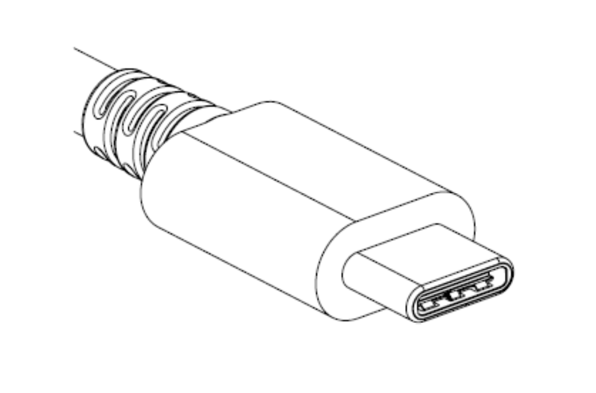
A single USB Type-C connector
When talking about USB-C, it’s important to start at the beginning. What do the words “USB-C” entail? Unsurprisingly, the answer is complicated. “USB Type-C” refers only to the physical connector and detail about how it is used, including some of the 24 pins it contains. Then there are the other terms. “USB 3.1” is the overall standard that encompasses the Type-C connector and new high-speed data busses (“USB SuperSpeed” and “SuperSpeedPlus”). In addition there is “USB Power Delivery” which describes power modes and even more pin assignments. We’re summarizing here, so go read the first post for more detail.
The second post devotes a formidable 1,200 words to providing an overview of the electrical specifications, configuration communication, and connector types for USB 3.1.
Marketing at its finest
The third post is devoted to USB Power Delivery. Power Delivery encompasses not only the new higher power modes supported (up to 100W!), but the ways to use the extra 10 or 13 pins available on the Type-C connector. This is both the boon and bane of USB-C, allowing apparently identical ports to carry common signals like HDMI or DisplayPort, act as analog audio outputs, and provide more exotic interfaces like PCIe 3.0 (in the form of Thunderbolt 3, which is a yet another thing this connector can be used for).
It should be clear at this point that the topics touched by “USB Type-C” are exceptionally complex. Save yourself the trouble of a 90MB specification zipfile and take a pass through [jason]’s posts to understand what’s happening. For even more detail about Power Delivery, he walks through sample transactions in a separate post.
When the ESP8266 was released, it was sold as a simple device that would connect to a WiFi network over a UART. It was effectively a WiFi modem for any microcontroller, available for just a few bucks. That in itself is awesome, but then the hackers got their hands on it. It turns out, the ESP8266 is actually a very capable microcontroller as well, and the newest modules have tons of Flash and pins for all your embedded projects.
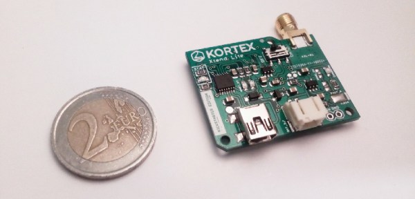
For [Amine]’s entry to the Hackaday Prize, he’s using the ESP8266 as the ultimate WiFi Swiss Army knife. The Kortex Xttend Lite is a tiny little WiFi repeater that’s capable of doing just about anything with a WiFi network, and with a bit of added hardware, can connect to Ethernet as well.
The hardware on this board sports an ESP8266-07S module, with two free GPIO pins for multiple functions. There’s a USB to UART in there, and a voltage regulator that’s capable of outputting 600mA for the slightly power hungry radio. There’s also an integrated battery management and charge controller, allowing this board to charge an off-the-shelf lithium cell and run for hours without any wires at all.
So, what can this board do? Just about everything you would want for a tiny little WiFi Swiss Army knife. There’s traffic shaping, port mapping, packet sniffing, and even support for mesh networking. There’s also an SMA connector on there, so grab your cantennas — this is a great way to extend a WiFi network, too.
This is a well-designed and well-executed project, and what makes this even more amazing is that this was done as one of [Amine]’s high school projects. Yes, it took about a year to finish this project, but it’s still amazing work for [Amine]’s first ‘high-complexity’ design. That makes it an excellent learning experience, and an awesome entry to this year’s Hackaday Prize.
Last time on Circuit VR, we looked at creating a very simple common emitter amplifier, but we didn’t talk about how to select the capacitor values, or much about why we wanted them. We are going to look at that this time, as well as how to use a second transistor in an emitter follower (or common collector) configuration to stiffen the amplifier’s ability to drive an output load.
Several readers wrote to point out that I’d pushed the Ic value a little high for a 2N2222. As it turns out, at least one of the calculations in the comments was a bit high. However, I’ve updated the post at the end to explore what was in the comments, and talk a bit more about how you compute power dissipation with or without LTSpice. If you read that post, you might want to jump back and pick up the update. Continue reading “Circuit VR: A Tale Of Two Transistors”→
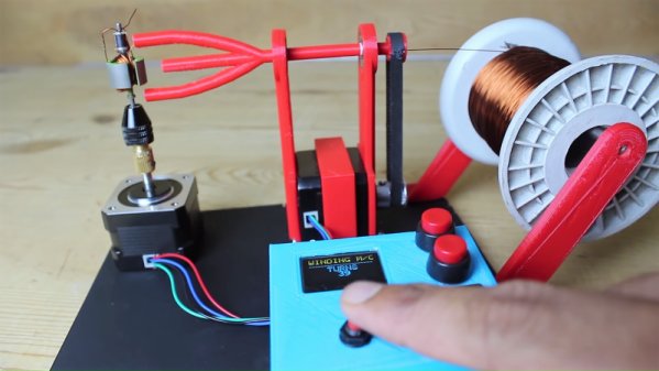
What’s your secret evil plan? Are you looking for world domination by building a machine that can truly replicate itself? Or are you just tired of winding motor rotors and other coils by hand? Either way, this automated coil winder is something you’re probably going to need.
We jest in part, but it’s true that closing the loop on self-replicating machines means being able to make things like motors. And for either brushed or brushless motors, that means turning spools of wire into coils of some sort. [Mr Innovative]’s winder uses a 3D-printed tube to spin magnet wire around a rotor core. A stepper motor turns the spinner arm a specified number of times, pausing at the end so the operator can move the wire to make room for the next loop. The rotor then spins to the next position on its own stepper motor, and the winding continues. That manual step needs attention to make this a fully automated system, and we think the tension of the wire needs to be addressed so the windings are a bit tighter. But it’s still a nice start, and it gives us some ideas for related coil-winding projects.
If you are in any way connected with radio, you will have encountered the low pass filter as a means to remove unwanted harmonics from the output of your transmitters. It’s a network of capacitors and inductors usually referred to as a pi-network after the rough resemblance of the schematic to a capital Greek letter Pi, and getting them right has traditionally been something of a Black Art. There are tables and formulae, but even after impressive feats of calculation the result can often not match the expectation.
The 30MHz low-pass filter, as QUCS delivered it.
Happily as with so many other fields, in recent decades the advent of affordable high-power computing has brought with it the ability to take the hard work out of filter design, Simply tell some software what the characteristics of your desired filter are, and it will do the rest. The results are good, and anyone can become a filter designer, but as is so often the case there remains a snag. The software calculates ideal inductances and capacitances for the desired cut-off and impedance, and in selecting the closest preferred values we modify the characteristics of the result and possibly even ruin our final filter. So it’s worth taking a look at the process here, and examining the effect of tweaking component values in this way.
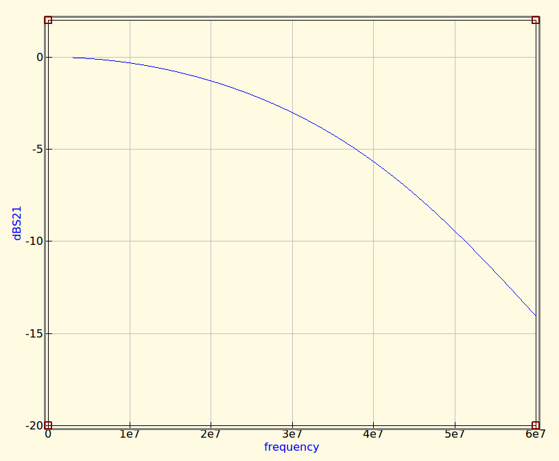
The idealised graph produced by QUCS for our filter.
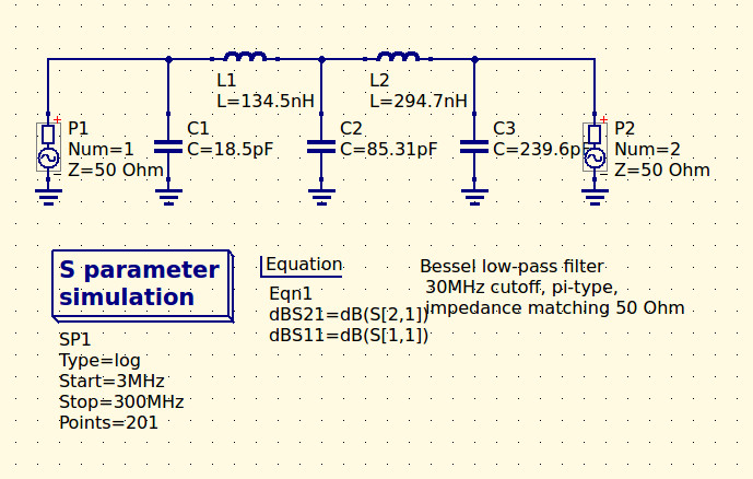
The filter we’re designing is simple enough, a 5th-order Bessel filter, and the software is the easy-to-use QUCS package on an Ubuntu Linux machine. Plug in the required figures and it spits out a circuit diagram, which we can then simulate to show a nice curve with a 3dB point right on 30MHz. It’s an extremely idealised graph, and experience has taught me that real-world filters using these designs have a lower-frequency cut-off point, but for our purposes here it’s a good enough start.
As previously mentioned, the component values are not preferred ones from a commercially available series, so I can’t buy them off the shelf. I can wind my own inductors, but therein lies a whole world of pain of its own and I’d rather not go there. RS, Mouser, Digikey, Farnell et al exist to save me from such pits of electronic doom, why on earth would I do anything else but buy ready-made?
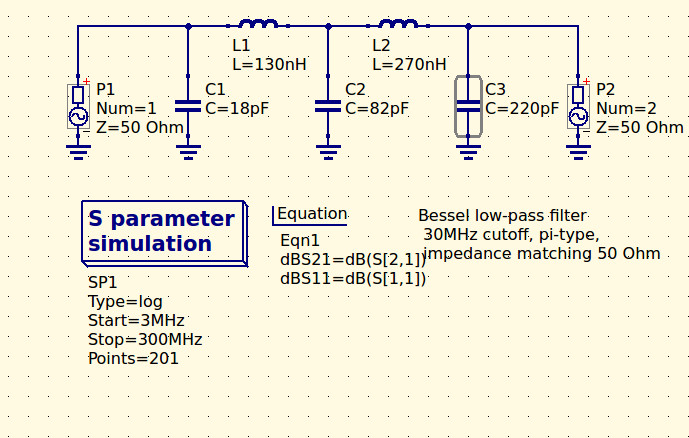
My revised filter circuit with off-the-shelf component values.
So each of the components in the above schematic needs moving up or down a little way to a preferred value. What effect will that have on the performance of my filter? Changing each value and re-running the simulation shows us the graph changing subtly each time, and it can sometimes be a challenge to adjust them without destroying the filter entirely. Particularly with the higher-order filters with more components in the network you can observe the effect of individual components on the gradient at different parts of the graph, but as a rule of thumb making values higher reduces the cut-off frequency and making them lower increases it. In my case I always pick higher values for that reason: my nearest harmonic I wish to filter is at double the frequency so I have quite some headroom to play with.
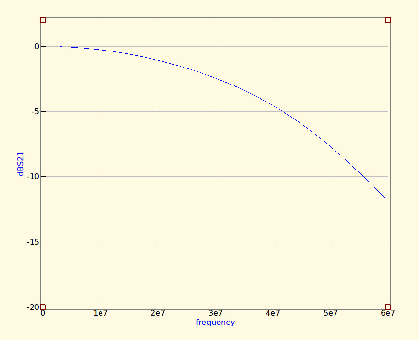
The revised curve from the filter with preferred values.
Having replaced my component values with preferred ones I can run the simulation again, and I can see from the resulting graph that I’ve been quite fortunate in not damaging its characteristics too much. As expected the cut-off frequency has shifted up a little, but the same curve shape has been preserved without any ripples appearing or it being made shallower.
If I were using this filter with a real transmitter I would ensure that I designed it with a cut-off at least a quarter higher than the transmission frequency. In practice I find the cut-off to be sharper and lower than the simulation leads one to expect, and for example, were I to use this one with a 30 MHz transmitter I’d find it attenuated the carrier by more than I’d consider acceptable. It must also be admitted that changing the component values in this way will also change the impedance of the filter from the calculated 50 ohms, however in practice this does not seem to be significant enough to cause a problem as long as the value changes are modest.
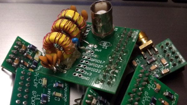
We haven’t made this filter, but in the past we’ve featured another one I did make, and by coincidence it was in the same frequency range. When I wrote a feature on automating oscilloscope readings, the example I used was the characterisation of a 7th-order 30 MHz low-pass filter. It might even be one of the ones in the header image, pulled from my random bag of filter boards for the occasion.
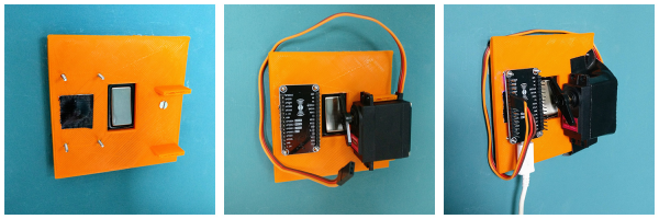
We’re not sure who designed [Max Glenister]’s place, but they had some strange ideas about interior door positioning. The door to his office is right next to a corner, yet it opens into the room instead of toward the wall. Well, that issue’s been taken care of. But the architect and the electrician got the last laugh, because now the light switch is blocked by the open door.
Folks, this is the stuff that IoT is made for. [Max] here solved one problem, and another sprang up in its place. What better reason for your maiden voyage into the cloud than a terrible inconvenience? He studied up on IoT servo-controlled light switching, but found that most of the precedent deals with protruding American switches rather than the rockers that light up the UK. [Max] got what he needed, though. Now he controls the light with a simple software slider on his phone. It uses the Blynk platform to send servo rotation commands to a NodeMCU, which moves the servo horn enough to work the switch. It’s simple, non-intrusive, and it doesn’t involve messing with mains electricity.
His plan was to design a new light switch cover with mounting brackets for the board and servo that screws into the existing holes. That worked out pretty well, but the weight of the beefy servo forced [Max] to use a bit of Gorilla tape for support. He’s currently dreaming up ways to make the next version easily detachable.
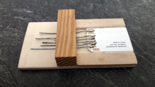
We feature hacks on this site of all levels of complexity. The simplest ones are usually the most elegant of “Why didn’t I think of that!” builds, but just occasionally we find something that is as much a bodge as a hack, a piece of work the sheer audacity of which elicits a reaction that has more of the “How did they get away with that! ” about it.
Such a moment comes today from [Robinlol], who has made an SD card socket. Why would you make an SD card socket when you could buy one is unclear, beyond that he didn’t want to buy one on an Arduino shield and considered manufacture his only option. Taking some pieces of wood, popsicle sticks, and paperclips, he proceeded to create a working SD card of such bodgeworthy briliance that even though it is frankly awful we still can’t help admiring it. It’s an SD card holder, and despite looking like a bunch of bent paperclips stuck in some wood, it works. What more could you want from an SD card holder?
Paperclips are versatile items. If an SD card holder isn’t good enough, how about using them in a CNC build?