Does The Cheese Grater Do A Great Grate Of Cheese?

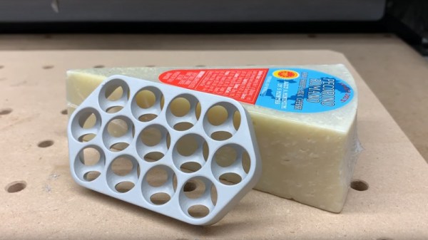
Apple’s newest Mac Pro with its distinctive machined grille continues to excite interest, but until now there has been one question on the lips of nobody. It’s acquired the moniker “Cheese grater”, but can it grate cheese? [Winston Moy] set out to test its effectiveness in the kitchen with a piece of Pecorino Romano, a great cheese.

Of course, the video is not really about cheese grating, but about the machining process to create that distinctive pattern of intersecting spherical holes. He doesn’t have a real Mac Pro because nobody does as yet, so like others his approach was to reverse engineer the manufacturing process. He takes us through the entire thing and the rationale behind his decisions as he makes a 13-hole piece of Mac Pro-like grill from a billet of aluminium. It’s first roughly cut with a pair of decreasing-size end mills, then finished with a ball mill. He’s added an extra cut to round off the sharp edge of the hole that isn’t there on the Mac.

An unexpected problem came when he machined the bottom and the holes began to intersect, it was clear that they were doing so wrongly. Turning the piece over must be done in the correct orientation, one to note for any other would-be cheese-grater manufacturers. Finally the piece is blasted for a satin finish, and then anodised for scratch-resistance.

So, the important question must be answered: does it grate? The answer’s no, the best it can manage is something close to a crumble. He doesn’t seem bothered though, we get the impression he likes eating cheese whatever its form. The whole process is in the video below the break.

For more Apple grille examination, take a look at this mathematical analysis.

Continue reading “Does The Cheese Grater Do A Great Grate Of Cheese?”

The Practical Approach To Keeping Your Laser In Focus

You could be forgiven for thinking that laser cutters and engravers are purely two dimensional affairs. After all, when compared to something like your average desktop 3D printer, most don’t have much in the way of a Z axis: the head moves around at a fixed height over the workpiece. It’s not as if they need a leadscrew to push the photons down to the surface.

But it’s actually a bit more complicated than that. As [Martin Raynsford] explains in a recent post on his blog, getting peak performance out of your laser cutter requires the same sort of careful adjustment of the Z axis that you’d expect with a 3D printer. Unfortunately, the development of automated methods for adjusting this critical variable on lasers hasn’t benefited from the same kind of attention that’s been given to the problem on their three dimensional counterparts.

Ultimately, it’s a matter of focus. The laser is at its most powerful when its energy is concentrated into the smallest dot possible. That means there’s a “sweet spot” in front of the lens where cutting and engraving will be the most efficient; anything closer or farther away than that won’t be as effective. As an example, [Martin] says that distance is exactly 50.3 mm on his machine.

The problem comes when you start cutting materials of different thicknesses. Just a few extra millimeters between the laser and your target material can have a big difference on how well it cuts or engraves. So the trick is maintaining that perfect distance every time you fire up the laser. But how?

One way to automate this process is a touch probe, which works much the same as it does on a 3D printer. The probe is used to find where the top of the material is, and the ideal distance can be calculated from that point. But in his experience, [Martin] has found these systems leave something to be desired. Not only do they add unnecessary weight to the head of the laser, but the smoke residue that collects on the touch probe seems to invariably mar whatever surface you’re working on with its greasy taps.

In his experience, [Martin] says the best solution is actually the simplest. Just cut yourself a little height tool that’s precisely as long as your laser’s focal length. Before each job, stick the tool in between the laser head and the target to make sure you’re at the optimal height.

On entry level lasers, adjusting the Z height is likely to involve turning some screws by hand. But you can always add a motorized Z table to speed things up a bit. Of course, you’ll still need to make sure your X and Y alignment is correct. Luckily, [Martin] has some tips for that as well.

Raspberry Pi 4 Just Released: Faster CPU, More Memory, Dual HDMI Ports

The Raspberry Pi 4 was just released. This is the newest version of the Raspberry Pi and offers a better CPU and more memory than the Raspberry Pi 3, dual HDMI outputs, better USB and Ethernet performance, and will remain in production until January, 2026.

There are three varieties of the Raspberry Pi 4 — one with 1GB of RAM, one with 2GB, and one with 4GB of RAM — available for $35, $45, and $55, respectively. There’s a video for this Raspberry Pi launch, and all of the details are on the Raspberry Pi 4 website.

A Better CPU, Better Graphics, and More Memory

The CPU on the new and improved Raspberry Pi 4 is a significant upgrade. While the Raspberry Pi 3 featured a Broadcom BCM2837 SoC (4× ARM Cortex-A53 running at 1.2GHz) the new board has a Broadcom BCM2711 SoC (a quad-core Cortex-A72 running at 1.5GHz). The press literature says this provides desktop performance comparable to entry-level x86 systems.

Of note, the new Raspberry Pi 4 features not one but two HDMI ports, albeit in a micro HDMI format. This allows for dual-display support at up to 4k60p. Graphics power includes H.265 4k60 decode, H.264 1080p60 decode, 1080p30 encode, with support for OpenGL ES, 3.0 graphics. As with all Raspberry Pis, there’s a component  composite video port as well tucked inside the audio port. The 2-lane MIPI DSI display port and 2-lane MIPI CSI camera port remain from the Raspberry Pi 3.

Continue reading “Raspberry Pi 4 Just Released: Faster CPU, More Memory, Dual HDMI Ports”

The Benefits Of Restoring A C64 With A Modern FPGA Board

The Commodore 64 was the highest selling computer of all time, and will likely forever remain that way due to the fragmentation of models in the market ever since. Due to this, it’s hardly surprising that it still has a strong following many years after its heyday. This means that the avid restorer has a wide range of parts and support available at the click of a button. [DusteD] is just one such person who had a busted-up C64 laying around, and decided to make it a project.

[DusteD] wanted to reuse the original case, and decided it should remain a Commodore 64 after an initial attempt at a mini-ITX swap went awry. Desiring a reliable machine, an Ultimate64 FPGA board was selected to replace the original faulty motherboard. This has the benefit of being hardware compatible with the classic C64, while allowing [DusteD] to tinker and program to his heart’s content, without having to worry about blowing up valuable original parts. It also provides several interesting modern features, like HDMI output, USB, and even Ethernet connectivity. This allows one to experiment with the platform without the hassles of all the inherent limitations of 1980s technology.

As a fan of the classic SID sound chip, [DusteD] was also highly interested in the audio output of the Ultimate64. Recordings were made of the emulated output from the FPGA, as well as the sound output from a real SID installed in the board, both through the mixed output and directly from the chip via a SIDTAP. Those interested can download the 800MB of recordings and compare the output; there’s a summary of the differences noted listed on the site as well.

[DusteD] makes a great argument for the benefits of building up a C64 rig in this way. It’s a great way to get started for those eager to explore the world of Commodore’s 8-bit hardware without the hassles and expenses of buying all the real gear. As it stands, the C64 aftermarket is so advanced now, that you can build an entirely new machine from scratch if you so desire. Go forth and enjoy!

Caching In On Program Performance

Most of us have a pretty simple model of how a computer works. The CPU fetches instructions and data from memory, executes them, and writes data back to memory. That model is a good enough abstraction for most of what we do, but it hasn’t really been true for a long time on anything but the simplest computers. A modern computer’s memory subsystem is much more complex and often is the key to unlocking real performance. [Pdziepak] has a great post about how to take practical advantage of modern caching to improve high-performance code.

If you go back to 1956, [Tom Kilburn’s] Atlas computer introduced virtual memory based on the work of a doctoral thesis by [Fritz-Rudolf Güntsch]. The idea is that a small amount of high-speed memory holds pieces of a larger memory device like a memory drum, tape, or disk. If a program accesses a piece of memory that is not in the high-speed memory, the system reads from the mass storage device, after possibly making room by writing some part of working memory back out to the mass storage device.

Continue reading “Caching In On Program Performance”

Hackaday Links Column Banner

Hackaday Links: June 16th, 2019

OpenSCAD has been updated. The latest release of what is probably the best 3D modeling tool has been in the works for years now, and we’ve got some interesting features now. Of note, there’s a customizer, for allowing parametrizing designs with a GUI. There’s 3D mouse support, so drag out that weird ball mouse from the 90s. You can export in SVG, 3MF, and AMF. Update your install of OpenSCAD now.

New Hampshire is the home of BASIC, and now there’s a sign on the side of the road saying so. This is a New Hampshire state historical marker honoring BASIC, invented at Dartmouth College in 1964. Interestingly, there are 255 historical markers in New Hampshire, usually honoring bridges and historical figures, which means there’s an off-by-one error depending on implementation.

Because robots a great way to get kids into technology — someone has to repair the future robot workers of the world — DJI has release the RoboMaster S1. It’s a robot with four Mecanum wheels, something like a Nerf turret, a camera, and WiFi. The best part? It’s programmable, either through Scratch or Python. Yes, it’s drag-and-drop programming for line following robots.

If you have a C by GE Smart Light Bulb and connect a new router to your home network, you will need to disassociate your C By GE Smart Light Bulb with your old network. To do this, you first need to turn your bulb on for eight seconds, then turn off for two seconds, then turn on for eight seconds, then turn off for two seconds. Then turn the bulb on for eight seconds, and finally turn the bulb off for two seconds. Finally, turn the bulb on for eight seconds, then turn the bulb off for two seconds. Your bulb should blink three times, indicating it has dissociated with the WiFi network. If this procedure does not work, your light bulb is running an older version of firmware. This is why you put a physical reset button on your stuff, people.

Have a lot of Raspberry Pi hats but you want to play around with the ESP32? No problem, because here’s a Pi-compatible GPIO ESP32 board. It needs a catchier name, but this is an ESP32 that’s mostly compatible with the 40-pin connector found on all Pis. Here’s a Crowd Supply link.


Split Flap Clock Keeps Time Thanks To Custom Frequency Converter

Why would anyone put as much effort into resurrecting a 1970s split-flap clock as [mitxela] did when he built this custom PLL frequency converter? We’re not sure, but we do like the results.

The clock is a recreation of the prop from the classic 1993 film, Groundhog Day, rigged to play nothing but “I Got You Babe” using the usual sound boards and such. But the interesting part was getting the clock mechanism keeping decent time. Sourced from the US, the clock wanted 120 VAC at 60 Hz rather than the 240 VAC, 50 Hz UK standard. The voltage difference could be easily handled, but the frequency mismatch left the clock running unacceptably slow.

That’s when [mitxela] went all in and designed a custom circuit to convert the 50 Hz mains to 60 Hz. What’s more, he decided to lock his synthesized waveform to the supply current, to take advantage of the long-term frequency control power producers are known for. The write-up goes into great detail about the design of the phase-locked loop (PLL), which uses an ATtiny85 to monitor the rising edge of the mains supply and generate the PWM signal that results in six cycles out for every five cycles in. The result is that the clock keeps decent time now, and he learned a little something too.

If the name [mitxela] seems familiar, it’s probably because we’ve featured many of his awesome builds before. From ludicrous-scale soldering to a thermal printer Polaroid to a Morse-to-USB keyboard, he’s always got something cool going on.