Growing Your Own Insulation

The latest craze in revolutionary materials science is no longer some carbon nanotube, a new mysterious alloy, or biodegradeable plastic. It seems as though a lot of new developments are coming out of the biology world, specifically from mycologists who study fungi. While the jury’s still out on whether or not it’s possible to use fungi to build a decent Star Trek series, researchers have in fact been able to use certain kinds of it to build high-performing insulation.

The insulation is made of the part of the fungus called the mycelium, rather than its more familiar-looking fruiting body. The mycelium is a strand-like structure of fungus which grows through materials in order to digest them. This could be mulch, fruit, logs, straw, crude oil, or even live insects, and you might have noticed it because it’s often white and fuzzy-looking. The particular type of mycelium used here is extremely resistant to changes in temperature so is ideal for making insulation. As a bonus, it can be grown, not manufactured, and can use biological waste products as a growing medium. Further, it can grow to fit the space it’s given, and it is much less environmentally harmful than existing forms of insulation.

As far as performance is concerned, a reporter from the BBC tested it in an interesting video involving a frozen chocolate bar and a blowtorch, discovering also that the insulation is relatively flame-retardant. Besides insulation, though, there are many more atypical uses of fungi that have been discovered recently including pest control and ethanol creation. They can also be used to create self-healing concrete.

Thanks to [Michael] for the tip!

Photo of fungal mycelium: Tobi Kellner [CC BY-SA 3.0]

3D Printer Warning: Heating Plastic To High Temps Is Not Healthy

If you’ve ever tried to cut a piece of acrylic with a tool designed to cut wood or metal, you know that the plastic doesn’t cut in the same way that either of the other materials would. It melts at the cutting location, often gumming up the tool but always releasing a terrible smell that will encourage anyone who has tried this to get the proper plastic cutting tools instead of taking shortcuts. Other tools that heat up plastic also have this problem, as Gizmodo reported recently, and it turns out that the plastic particles aren’t just smelly, they’re toxic.

The report released recently in Aerosol Science and Technology (first part and second part) focuses on 3D printers which heat plastic of some form or other in order to make it malleable and form to the specifications of the print. Similar to cutting plastic with the wrong tool, this releases vaporized plastic particles into the air which are incredibly small and can cause health issues when inhaled. They are too small to be seen, and can enter the bloodstream through the lungs. The study found 200 different compounds that were emitted by the printers, some of which are known to be harmful, including several carcinogens. The worst of the emissions seem to be released when the prints are first initiated, but they are continuously released throuhgout the print session as well.

Perhaps it’s not surprising that aerosolized plastic is harmful to breathe, but the sheer magnitude of particles detected in this study is worth taking note of. If you don’t already, it might be good to run your 3D printer in the garage or at least in a room that isn’t used as living space. If that’s not possible, you might want to look at other options to keep your work area safe.

Thanks to [Michael] for the tip!

High Voltage Measurement Is Shockingly Safe

With the right equipment and training, it’s possible to safely work on energized power lines in the 500 kV range with bare hands. Most of us, though, don’t have the right equipment or training, and should take great care when working with any appreciable amount of voltage. If you want to safely measure even the voltages of the wiring in your house there’s still substantial danger, and you’ll want to take some precautions like using isolated amplifiers.

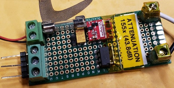
While there are other safe methods for measuring line voltage or protecting your oscilloscope, [Jason]’s isolated amplifier method uses high voltage capacitors to achieve isolation. The input is then digitized, sent across the capacitors, and then converted back to an analog signal on the other side. This project makes use of a chip from TI to provide the isolation, and [Jason] was able to build it on a perfboard while making many design considerations to ensure it’s as safe as possible, like encasing high voltage sections in epoxy and properly fusing the circuit.

[Jason] also discusses the limitations of this method of isolation on his site, and goes into a lot of technical details about the circuit as well. It probably wouldn’t get a UL certification, but the circuit performs well and even caught a local voltage sag while he was measuring the local power grid. If this method doesn’t meet all of your isolation needs, though, there are a lot of other ways to go about solving the problem.

Analog Clock Goes Digital, Or Vice Versa

Designing a good clock takes a lot of considerations. It’s not just hands, faces, and numbers anymore; there are also word clocks, electronic clocks, marble clocks, or water clocks, and just about anything else imaginable can be used to tell time. Of course, electronic clocks are great for their versatility, and this one shows off an analog-looking clock that is (of course) digital, leveraging all of the perks of analog with all of the upsides of digital electronics.

One of the key design considerations that [Sasa] had while building this piece was that it needed to be silent. LEDs certainly fit that description, so the decision was made to go with an WS2812b ring. It runs using a STM ST32F103 Nucleo board (and a cheaper version of it in later versions of this clock) which shows a red LED for the current hour, yellow LEDs for the traditional analog clock divisions, a green LED for the current minute, and glows the rest of the LEDs up to the current minute with a rainbow pattern.

This is a really clean, simple build with good design at its core, and would be easy to replicate if you’re looking for an eye-catching clock to build. As a bonus, all of the schematics and code are available on the project site, so everything you need is there. If you’re looking for more inspiration, there are some clocks that are even more unique, like this marble clock that is a work of art — but is anything but silent.

Smooth Moves From Cheap Motors

Building an electric motor isn’t hard or technically challenging, but these motors have very little in the way of control. A stepper motor is usually employed in applications that need precision, but adding this feature to a motor adds complexity and therefore cost. There is a small $3 stepper motor available, but the downside to this motor is that it’s not exactly the Cadillac of motors, nor was it intended to be. With some coaxing, though, [T-Kuhn] was able to get a lot out of this small, cheap motor.

To test out the motors, [T-Kuhn] built a small robotic arm. He began by programming his own pulse generating algorithm that mimics a sine wave in order to smooth out the movement of the motor. An Arduino isn’t fast enough to do these computations, though, so he upgraded to using the ESP32. He also was able to implement the inverse kinematics on his own. The result of all this work for a specific platform and motor type is a robotic arm that has a very low cost but delivers performance of much more expensive hardware.

The robot arm was built by [T-Kuhn] too, and all of the details on that build, as well as all the schematics and code, are available on the project site if you need a low-cost robot arm or a good stepper motor controller for a low cost. There are many other ways of getting the most out of other types of low-cost motors as well.

Continue reading “Smooth Moves From Cheap Motors”

Memory Mapping Methods In The Super Nintendo

Not only is the Super Nintendo an all-around great platform, both during its prime in the 90s and now during the nostalgia craze, but its relative simplicity compared to modern systems makes it a lot more accessible from a computer science point-of-view. That means that we can get some in-depth discussion on how the Super Nintendo actually does what it does, and understand most of it, like this video from [Retro Game Mechanics Explained] which goes into an incredible amount of detail on the mechanics of the SNES’s memory system.

Two of the interesting memory systems the SNES uses are called DMA and HDMA. DMA stands for direct memory access, and is a way for the Super Nintendo to access memory independently of the CPU. The advantages to this are that it’s incredibly fast compared to more typical methods of accessing memory. This isn’t particulalry unique, but the HDMA system is. It allows the SNES to do all kinds of interesting tricks with its video output display like changing color gradients and doing all kinds of masking effects.

If you’re interested in the inner workings of classic consoles like the SNES, this video gets way down in the weeds in the system itself. It’s interesting to see how programmers were able to squeeze more capability from these limited (by modern standards) systems by manipulating memory like the DMA and HDMA systems do.  [Retro Game Mechanics Explained] is a great resource for exploring in-depth aspects of lots of classic games, like how speedrunners can execute arbitrary code in old Mario games.

Continue reading “Memory Mapping Methods In The Super Nintendo”

Arduino Gets A Command Line Interface

When using an Arduino, at least once you’ve made it past blinking LEDs, you might start making use of the serial connection to send and receive information from the microcontroller. Communicating with the board while it’s interacting with its environment is a crucial way to get information in real-time. Usually, that’s as far as it goes, but [Pieter] wanted to take it a step farther than that with his command line interpreter (CLI) for the Arduino.

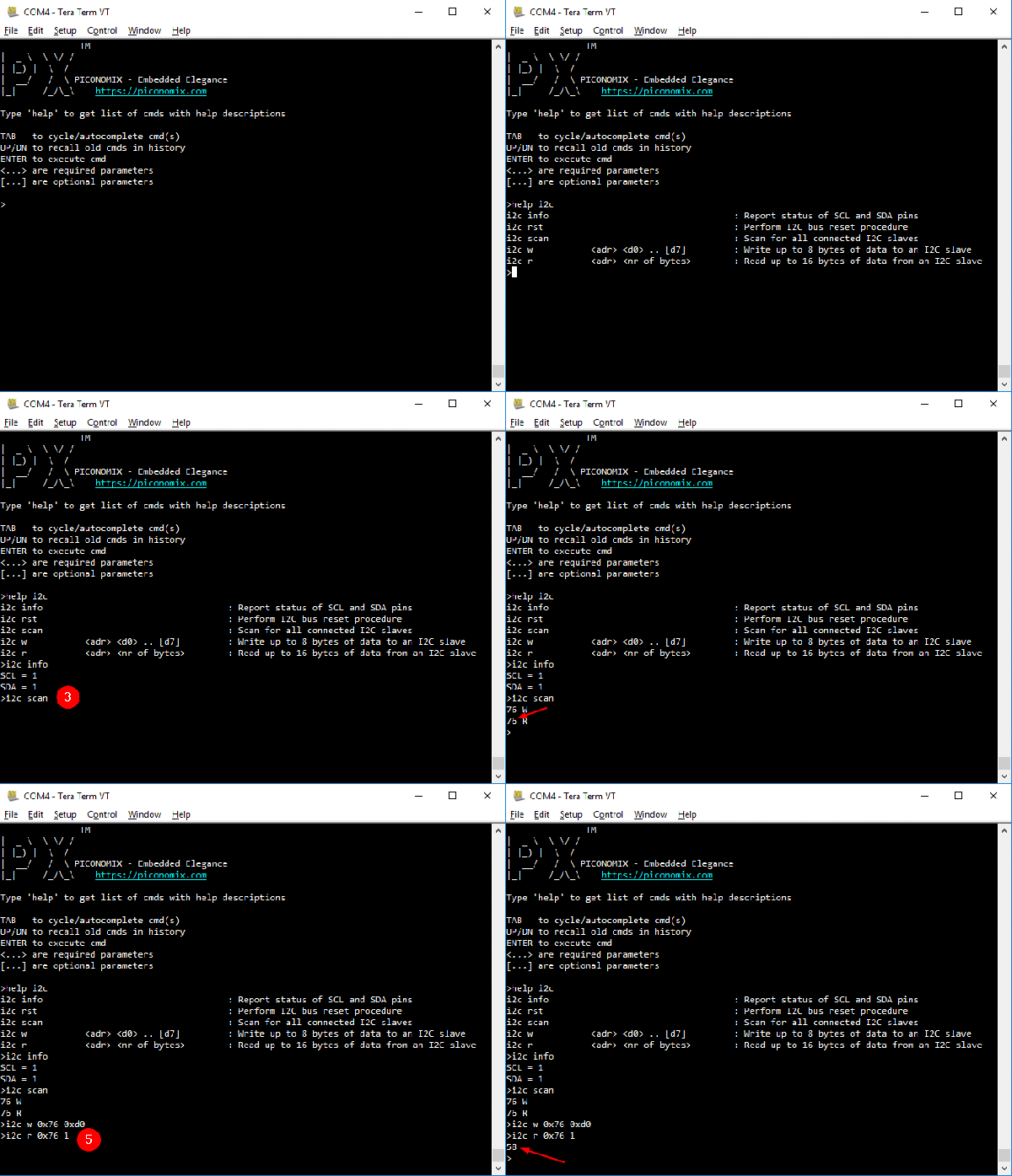
The CLI allows the user to run Unix-like commands directly on the Arduino. This means control of GPIO and the rest of the features of the microcontroller via command line. The CLI communicates between the microcontroller and the ANSI/VT100 terminal emulator of your choosing on your computer, enabling a wealth of new methods of interacting with an Arduino.

The CLI requires a hex file to be loaded onto the Arduino that you can find at a separate site, also maintained by [Pieter]. Once that’s running, you can get all of that sweet command line goodness out of your Arduino. [Pieter] also has some examples on his project page, as well as the complete how-to to get this all set up and running. There’s a lot going on in the command line world, in Linux as well as windows. So there’s plenty to explore there as well.