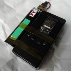
For devices that are destined for momentary and infrequent use as well as battery power, some kind of power saving is pretty much a required feature. For example, when [PJ Allen] turned two ESP8266-based NodeMCU development boards into a replacement wireless remote garage door opener, a handy USB power bank ended up serving as a bit of a cheat when migrating the remote away from the workbench. Instead of moving the board from USB to battery power and implementing some kind of sleep mode or auto-off, [PJ Allen] simply plugged in a USB power bank and let it do all the work.
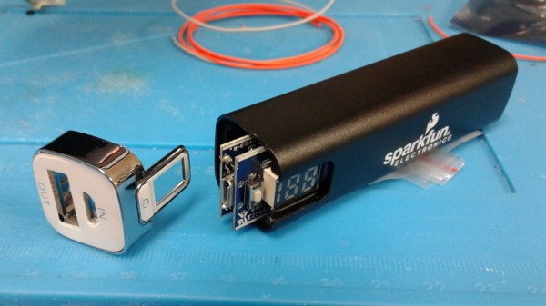
This is how the feature works: some USB power banks turn themselves off unless they detect a meaningful current draw. That means that if the power bank is charging a phone, it stays on, but if it’s only lighting up a few LEDs, it’ll turn itself off. This feature can be a frustrating one, but [PJ Allen] realized that it could actually be useful for a device like his garage door remote. Turning on the power bank delivers 5 V to the NodeMCU board and allows it to work, but after about fifteen seconds, the power bank turns itself off. Sure, strapping a power bank to the remote makes the whole thing bigger than it needs to be, but it’s a pretty clever use of the minimum load as an effortless auto-off feature.
The NodeMCU boards in [PJ Allen]’s DIY remote use ESP-NOW for their wireless communications, a nifty connectionless protocol from Espressif that we’ve seen used in other projects as well, such as this ESP32-based walkie-talkie.