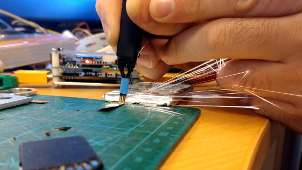
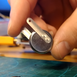
 Did you ever see a thin metal tab bonded to a battery terminal with little pock marks? That’s the work of a spot welder. Spot welding is one of those processes that doesn’t offer much in the way of alternatives; either one uses a spot welder to do the job right, or one simply does without. That need is what led [Erwin Ried] to purchase a small, battery-powered spot welder from a maker in Korea and test it out on nickel strips.
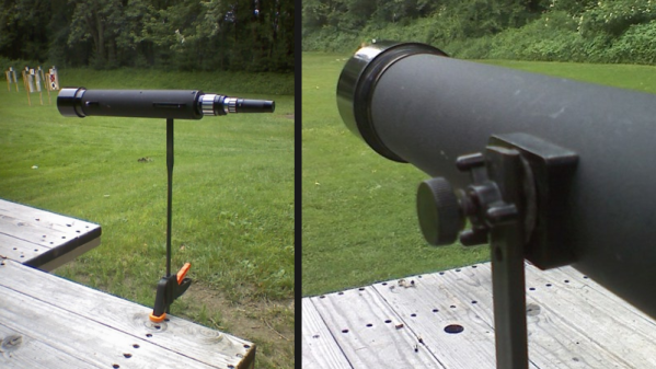
The spot welder [Erwin] used is the work of a user by the name of [aulakiria] (link is Korean, machine translation here) and is designed to be portable and powered by batteries commonly used for RC. [Erwin] is delighted with the results, and demonstrates the device in the video embedded below.
Spot welder projects see a lot of DIY, some of which are successful while others are less so. Our own [Sean Boyce] even gave making a solar-powered spot welder a shot, the results of which he described as “nearly practical!”
Continue reading “Testing A Battery-Powered Mini Spot Welder”
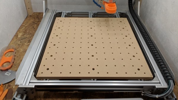
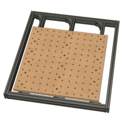 [Adam Haile] has been spending some time improving his CNC router and his latest change is