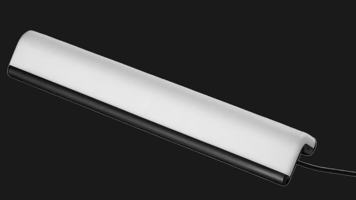
The IKEA SKAFTSÄRV is an economical LED accent lamp, but while highly affordable it has only fixed lighting options. [simoneluconi] shows how it can easily be turned into a fully-configurable, WLED-connected, WiFi-enabled RGB lamp with little more than an ESP32-based board.
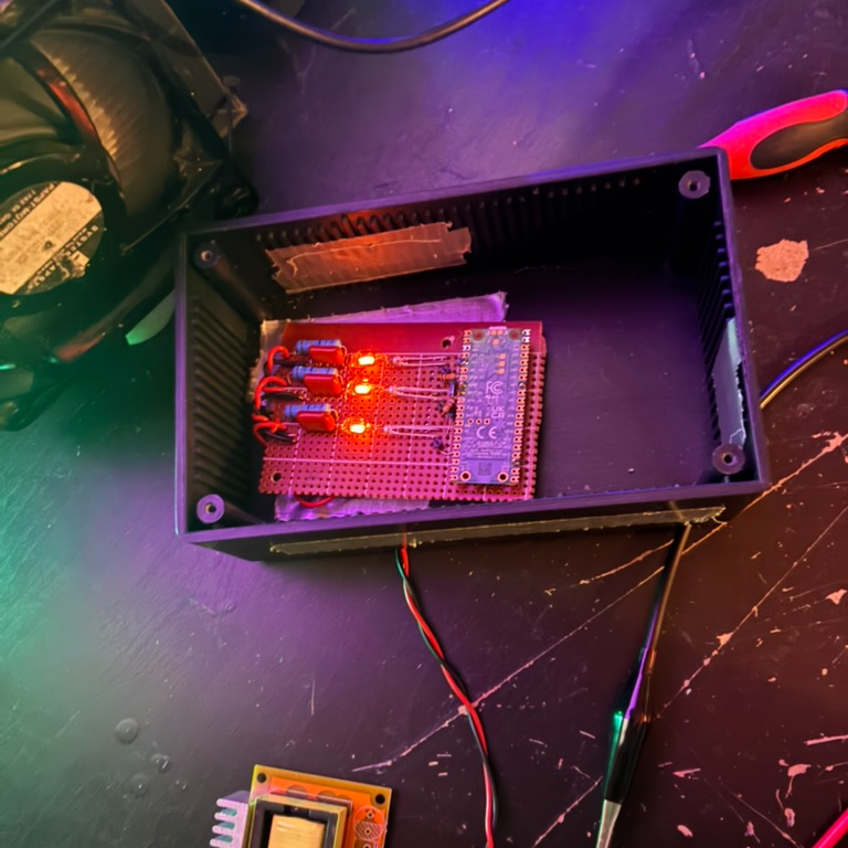
To do this, the control board of the lamp gets replaced with an ESP32-C3 Super Mini board. Control and automation comes from WLED, open-source software that offers flexible automation and control for LED lights with a wide range of features, including native Android and iOS apps.
Modifying the SKAFTSÄRV lamp is fairly straightforward, but opening the unit does require breaking some glued seams to get inside. Once that’s done, the replacement board fits nicely into the housing and the unit can be closed back up. As far as WLED is concerned, the new lamp has 30 LEDs, WS281x type, GRB color order.
The end result is a stylish accent lamp with built-in diffusor and mount that can be controlled over WiFi with all the features WLED brings, such as easy integration with Home Assistant.
This isn’t the first time IKEA’s LED lighting has been given a powerup. Their pixel-style LED wall-mounted OBEGRÄNSAD, which displays a few canned animations out of the box, got considerably enhanced with a new controller.
Thanks [Crash] for the tip!