Shape shifters have long been the stuff of speculative fiction, but researchers in China have developed a magnetoactive phase transitional matter (MPTM) that makes Odo slipping through an air vent that much more believable.
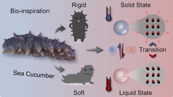
Soft robots can squeeze into small spaces or change shape as needed, but many of these systems aren’t as strong as their more mechanically rigid siblings. Inspired by the sea cucumber’s ability to manipulate its rigidity, this new MPTM can be inductively heated to a molten state to change shape as well as encapsulate or release materials. The neodymium-iron-boron (NdFeB) microparticles suspended in gallium will then return to solid form once cooled.
Applications in drug delivery, foreign object removal, and smart soldering (video after the break) probably have more real world impact than the LEGO minifig T1000 impersonation, despite how cool that looks. While a pick-and-place can do better soldering work on a factory line, there might be repair situations where a magnetically-controlled solder system could come in handy.
We’ve seen earlier work with liquid robots using gallium and bio-electronic hybrids also portending the squishy future of robotics.
Continue reading “Phase Change Materials For Flexible And Strong Robots”