Copying High Security Keys With OpenSCAD And Light

The ability to duplicate keys with a 3D printer is certainly nothing new, but so far we’ve only seen the technique used against relatively low hanging fruit. It’s one thing to print a key that will open a $15 Kwikset deadbolt from the hardware store or a TSA-approved “lock” that’s little more than a toy, but a high-security key is another story. The geometry of these keys is far more complex, making them too challenging to duplicate on a consumer-level printer. Or at least, you’d think so.

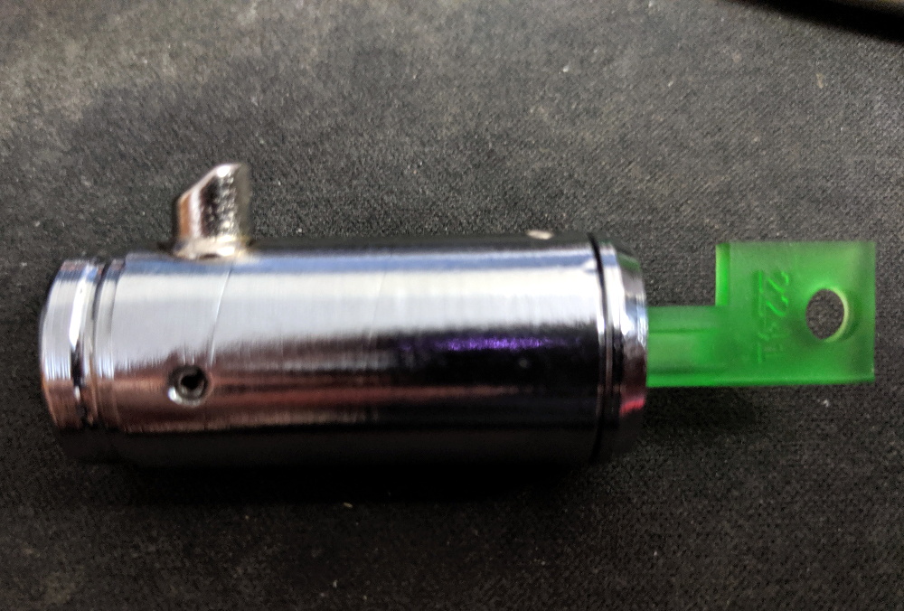
Inspired by previous printed keys, [Tiernan] wanted to see if the techniques could be refined for use against high security Abloy Protec locks, which are noted for their resistance to traditional physical attacks such as picking. The resulting STLs are, unsurprisingly, beyond the capabilities of your average desktop FDM printer. But with a sub-$300 USD Anycubic Photon DLP printer, it’s now possible to circumvent these highly regarded locks non-destructively.

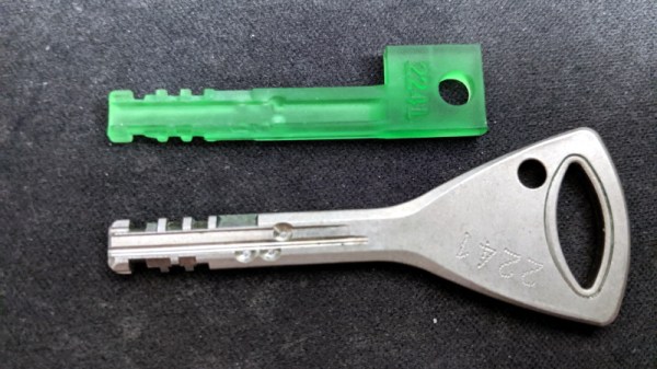
Of course, these keys are far too intricate to duplicate from a single picture, so you’ll need to have the physical key in hand and decode it manually. [Tiernan] wisely leaves that step of the process out, so anyone looking to use this project will need to have a good working knowledge of the Abloy Protec system. Hopefully this keeps bad actors from doing anything too nefarious with this research.

Once you have the decoded values for the key you want to duplicate, you just need to provide them to the OpenSCAD library [Tiernan] has developed and print the resulting STL on your sufficiently high-resolution printer. Generally speaking, the parts produced by resin-based printing have a high tensile strength but are very brittle, so perhaps not the kind of thing you want to stick in your expensive Abloy lock. That said, there are some “Tough Resin” formulations available now which produce parts that are at least as strong as those made with thermoplastics. So while the printed keys might not be strong enough for daily use, they’ll certainly work in a pinch.

A Virtual Tour Of The B-17

The Boeing B-17 “Flying Fortress” is arguably the most recognizable aircraft of the Second World War. Made infamous by the daring daylight strategic bombing runs they carried out over Germany, more than 12,000 of these four-engined bombers were produced between 1939 and 1945. Thanks to the plane’s renowned survivability in battle, approximately 60% of them made it through the war and returned home to the United States, only to be rounded up in so-called “boneyards” where they were ultimately cut up and sold as scrap. Today there are fewer than 50 intact Boeing B-17s left in the world, and of those, only 11 remain airworthy.

One of them is Nine-O-Nine, a B-17G built in April 7, 1945. This particular aircraft was built too late to see any combat, although in the 1950s she was fitted with various instruments and exposed to three separate nuclear blasts for research purposes. It’s actually not the real Nine-O-Nine either, the original was scrapped after it completed eighteen bombing runs over Berlin. Without a combat record of its own, this bomber was painted to look like the real Nine-O-Nine in honor of its incredible service record of never losing a crewman.

Since 1986, Nine-O-Nine has been owned by the Collings Foundation, who operate her as a living history exhibit. The bomber flies around the United States with an entourage of similarly iconic WWII aircraft as part of the Wings of Freedom Tour, stopping by various airports and giving the public a chance to climb aboard and see the pinnacle of mid-1940s strategic bombing technology. History buffs with suitably deep pockets can even book a seat on one of the scheduled 30-minute flights that take place at every stop on the Tour.

I was lucky enough to have the The Wings of Freedom Tour pass through my area recently, and couldn’t pass up the opportunity to experience this incredible aircraft first hand. The fact that I’m equal parts a coward and miser kept me from taking a ride aboard the 74 year old Nine-O-Nine, at least for now, but I made sure to take plenty of pictures from inside this lovingly restored B-17G while it was safely on the ground.

Continue reading “A Virtual Tour Of The B-17”

RPi Tank Invades Living Room, Teaches OpenCV

If you’re looking for a simple project to start exploring the intersection of OpenCV and robotics, then the RPi Tank created by [Vishal Varghese] might be a good place to start. A Raspberry Pi and a few bits of ancillary hardware literally taped to the top of a toy M1 Abrams tank becomes a low-cost platform for testing out concepts such as network remote control and visual line following. Sure, you don’t need to base it around an Abrams tank, but if you’re going to do it you might as well do it with style.

As this is more of a tech demonstrator, the hardware details are pretty minimal. [Vishal] says you just need a relatively recent version of the Raspberry Pi, a MotoZero motor controller, and a camera module. To provide juice for the electronics you don’t need anything more exotic than a USB power bank, which in his case has been conveniently attached to the top of the turret. He doesn’t provide exact details on how the MotoZero gets wired into the Abram’s motors, but we imagine it’s straightforward enough that the average Hackaday reader probably doesn’t need it spelled out for them.

Ultimately, the software is the heart of this project, and that’s where [Vishal] really delivers. He’s provided sample Python scripts ordered by their level of complexity, from establishing a network connection on the Raspberry Pi to following a line of tape on the ground. Whether used together or examined individually, these scripts provide a great framework to get your first project rolling. Literally.

Line following robots, in their many forms, have been a favorite hacker project for years. Whether they home in with an analog circuit or replace the lines with hidden wires, they’re a great way to get started with semi-autonomous robotics.

Punch Through Switches Gears, Shucks Beans

Do you own a LightBlue Bean or Bean+ from Punch Through? If you don’t have one now, you probably never will, as the company has recently announced they’re no longer selling or supporting the Bluetooth Low Energy microcontrollers. The company says that after selling more than 100,000 Bean devices, the challenge of keeping up with a constantly evolving software ecosystem became too difficult, and they are instead going to focus their efforts on advising other companies on how to best develop Bluetooth products.

Frankly, that sounds a bit like getting advice on how to build a fully armed and operational battle station from the Empire, but who are we to judge. While the Bean family of devices clearly wasn’t able to go the distance, Punch Through at least got them out the door and supported them for longer than many might have expected given the increased competition in the BLE market. It’s not hard to do the math: the LightBlue Bean retailed for around $35 USD, and today you can get a BLE-capable ESP32 for five bucks.

So what happens to all those Beans out in the wild? Normally, the parent company dropping support for a microcontroller wouldn’t be that big of a deal, but this time around we have the “Bean Loader” to contend with. This piece of software is used to push code to the device over Bluetooth, and it’s possible that the constant march of operating system upgrades (especially on mobile devices) will eventually break it. Long story short, there’s nothing to worry about in the short term. But down the road, these Beans might be baked.

Luckily, Punch Through did provide some pretty extensive documentation for the Beans. If there’s significant demand, we imagine the community will do their best to take over development of whatever ancillary software is required to keep the hardware usable for the foreseeable future. Speaking of which, the schematics and PCB layouts for both the Bean and Bean+ have been released under the Creative Commons Attribution 4.0 International license, so it’s not outside the realm of possibility that somebody else might put them back into production.

[Thanks to Chris for the tip.]

A Hard Rocking Arduino Visualization Shield

Over the summer [ElectroSmash] put the finishing touches on the Arduino Audio Meter, a shield for the Arduino Uno that visualizes various aspects of an incoming audio signal on a set of four 8×8 LED dot matrices. Obsentisibly it’s for use on a guitar pedalboard, but thanks to the incredible documentation and collection of example code provided by the team, the project promises to be an excellent platform for all sorts of audio experimentation.

Incoming audio is amplified with an MCP6002 and fed into the Uno’s Analog to Digital Converter, where it’s processed via whatever Sketch the user has uploaded. User input is provided by a digital encoder with push-button. A set of four MAX7219 chips control the entire 256-pixel matrix with just three pins on the Arduino. The resolution of the display allows the Arduino Audio Meter to show more than just a simple VU meter, it can even do text and basic graphics.

[ElectroSmash] provides various Sketches for use with the Arduino Audio Meter that provide the expected repertoire of audio visualizations, but they also provide a number of interesting Sketches to expand the capabilities of the device in unexpected ways. Some of them could be useful for a stage musician, such a tool to tune your guitar, whereas others are fun uses of the hardware such as a game of “Snake”.

With the entire project released as open source, users are free to run wild with the Arduino Audio Meter. Writing your own custom software is an obvious first step to making the project your own, but adding additional hardware features and functions certainly aren’t out of the question either.

Our very own [Lewin Day] once walked us through the effort involved in building boutique guitar pedals, and while the Audio Audio Meter’s capabilities are somewhat limited as it doesn’t have the ability to change the audio going through it, we’re still interested in seeing what the community will come up with once they have an easy way to bring their ideas to life.

Continue reading “A Hard Rocking Arduino Visualization Shield”

RGB Lamp With Micro:Bit Powered Gesture Control

The Micro:bit is a very neat piece of hardware that, frankly, we don’t see enough of. Which made us all the more interested when [Manoj Nathwani] wrote in to tell us about the gorgeous 3D printed RGB LED lamp he created that uses the BBC-endorsed microcontroller to perform basic gesture detection. Purists will likely point out that an Arduino Pro Mini is tagging along to handle interfacing with the LEDs, but it’s still a good example of how quick you can get a project up and running with MicroPython on the Micro:bit.

[Manoj] used eight NeoPixel Sticks, a NeoPixel Ring, and a few scraps of perfboard to construct a three dimensional “bulb” to fill the void inside the printed diffuser. They’re chained together so all the elements appear as a single addressable strip, which made the rest of the project a bit easier to implement. It might not be pretty, but it gets the job done and it’s not like you’ll ever see it again once installed in the lamp anyway.

The Micro:bit and Arduino co-pilot live in the base of the lamp, and the single USB cable to provide power (and the ability to update the device’s firmware) is run out the bottom to give the whole thing a clean and professional look. For those wondering why the Arduino has tagged along, [Manoj] says he couldn’t get the NeoPixel libraries to play nicely with the Micro:bit so he’s using the Arduino essentially as a mediator.

Right now the only gesture that’s detected on the Micro:bit is a simple shake, which tells the Arduino to toggle the light show on and off. But in the future, [Manoj] plans to implement more complex gestures which will trigger different animations. As he explains in the blog post, gesture recognition with the Micro:bit is incredibly simple, so it should be easy to come up with a bunch of unique ways to interface with the lamp.

Color changing LED lamps are a favorite project of hackers, and we’ve seen examples built with everything from glass and copper to laser-cut pieces of wood and veneer. While you might prefer to skip the gesture control for an ESP8266 and UDP, we think this project is another strong entry into this popular genre.

A Stylish Home For Your Next ESP Project

The ESP8266 and ESP32 are fast becoming the microcontroller of choice for, well, everything. But one particular area we’ve seen a lot of activity in recently is home automation; these boards make it so incredibly easy and cheap to get your projects online that putting together your own automation system is far more appealing now than it’s ever been. Capitalizing on that trend, [hwhardsoft] has been working on a ESP enclosure that’s perfect for mounting on the living room wall.

Of course, there’s more to this project than an admittedly very nice plastic box. The system also includes a ILI9341 2.4 inch touch screen LCD, an integrated voltage regulator, and even a section of “perfboard” that gives you a spot to easily wire up ad-hoc circuits and sensors. You don’t even need to switch over to the bare modules either, as the PCB is designed to accommodate common development boards such as the Wemos D1 Mini and NodeMCU.

Despite its outward appearance, this project is very much beginner friendly. Utilizing through hole components, screw down terminals, and a impeccably well-labeled silkscreen, you won’t need to be a hardware expert to produce a very slick gadget the whole family can appreciate.

Much like the HestiaPi project we covered a few months back, this project takes a cheap and readily available development board and turns it into something that has all the trappings of a commercial offering. These projects are reminders that the line between built and bought is only getting blurrier as time goes on.

Continue reading “A Stylish Home For Your Next ESP Project”