The art of the electronic conference badge has evolved over the last decade or more, such that for an individual example to be of note it now has to include some exceptional features. Perhaps a function that might previously have been considered impossible in a badge, or maybe an unusually beautiful design, an entertaining and compelling functionality, or it simply pushes the capabilities of an otherwise limited device in an unusually ingenious way. The badge from the recent Hacker Hotel 2020 comes from the same badge team that created the software platform derived from the SHA 2017 badge, and it ticks many of these boxes by combining a genuine work of art with a set of delightfully intricate puzzles at enough levels to interest all participants in the event.

Augmented Reality Aids In The Fight Against COVID-19
“Know your enemy” is the essence of one of the most famous quotes from [Sun Tzu]’s Art of War, and it’s as true now as it was 2,500 years ago. It also applies far beyond the martial arts, and as the world squares off for battle against COVID-19, it’s especially important to know the enemy: the novel coronavirus now dubbed SARS-CoV-2. And now, augmented reality technology is giving a boost to search for fatal flaws in the virus that can be exploited to defeat it.
The video below is a fascinating mix of 3D models of viral structures, like the external spike glycoproteins that give coronaviruses their characteristic crown appearance, layered onto live video of [Tom Goddard], a programmer/analysts at the University of California San Francisco. The tool he’s using is called ChimeraX, a molecular visualization program developed by him and his colleagues. He actually refers to this setup as “mixed reality” rather than “augmented reality”, to stress the fact that AR tends to be an experience that only the user can fully appreciate, whereas this system allows him to act as a guide on a virtual tour of the smallest of structures.
Using a depth-sensing camera and a VR headset, [Tom] is able to manipulate 3D models of the SARS virus — we don’t yet have full 3D structure data for the novel coronavirus proteins — to show us exactly how SARS binds to its receptor, angiotensin-converting enzyme-2 (ACE-2), a protein expressed on the cell surfaces of many different tissue types. It’s fascinating to see how the biding domain of the spike reaches out to latch onto ACE-2 to begin the process of invading a cell; it’s also heartening to watch [Tom]’s simulation of how the immune system responds to and blocks that binding.
It looks like ChimeraX and similar AR systems are going to prove to be powerful tools in the fight against not just COVID-19, but in all kinds of infectious diseases. Hats off to [Tom] and his team for making them available to researchers free of charge.
Continue reading “Augmented Reality Aids In The Fight Against COVID-19”

Interplanetary Whack-A-Mole: NASA’s High-Stakes Rescue Plan For InSight Lander’s Science Mission
People rightly marvel at modern surgical techniques that let surgeons leverage the power of robotics to repair the smallest structures in the human body through wounds that can be closed with a couple of stitches. Such techniques can even be applied remotely, linking surgeon and robot through a telesurgery link. It can be risky, but it’s often a patient’s only option.
NASA has arrived at a similar inflection point, except that their patient is the Mars InSight lander, and the surgical suite is currently about 58 million kilometers away. The lander’s self-digging “mole” probe needs a little help getting started, so they’re planning a high-stakes rescue attempt that would make the most seasoned telesurgeon blanch: they want to use the lander’s robotic arm to press down on the mole to help it get back on track.

Ultimate Medical Hackathon: How Fast Can We Design And Deploy An Open Source Ventilator?
[Gui Cavalcanti], whose name you might recognize from MegaBots, got on a call with a medical professional in San Francisco and talked about respirators. The question being, can we design and deploy an open source version in time to help people?
Unnerving reports from Italy show that when the virus hits the susceptible population groups the device that becomes the decider between life and death is a ventilator. Unfortunately they are in short supply.
The problem gets tricky when it comes to what kind of respirator is needed CPAP, BIPAP, or Hi-Flo oxygen NIV are all out. These systems aerosolize the virus making it almost guaranteed that anyone around them will get infected.
What we need is a Nasal cannula-based NIV. This system humidifies air, mixes it with oxygen and then pushes a constant stream of it into people’s lungs. If we can design a simple and working system we can give those plans to factories around the globe and get these things made. If the factories fail us, let’s also have a version people can make at home.
If you aren’t sure if a ventilator is something you can work on there are other problems. Can you make algorithms to determine if a person needs a ventilator. Can we recycle n95 masks? Can we make n95 masks at home? Workers also require a negative pressure tent for housing patients. This will be especially useful if we need to build treatment facilities in gyms or office spaces. Lastly if you’re a medical professional, can you train people how to help?
Let’s beat this thing. The ultimate medical hackathon begins.
An RF Engineer’s FPGA Learning Journey
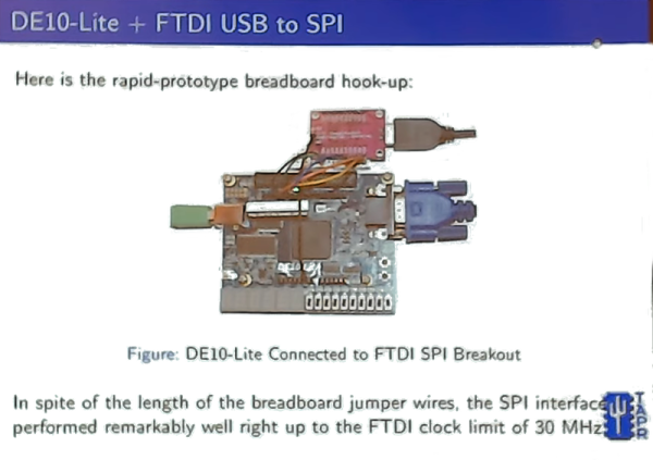
[KF5N] admits he’s not a digital design engineer; he’s more into the analog RF side of things. But he’s recently taken on a project to communicate between a Ubuntu box and an Intel MAX10 FPGA. He did a presentation at a recent ham radio convention about what he’d learned and how you could get started.
The video talks a lot about the Intel (used to be Altera). However, the nearly 40 minute video after the break isn’t a step-by-step tutorial so even if you are interested in other devices, you’ll probably enjoy watching it. If you’ve programmed even one FPGA, this video likely won’t hold your interest — you aren’t the target audience. However, at about 00:31 he does recommend some books and some very inexpensive FPGA boards, so it’s not a total wash.
[KF5N] talks about what an FPGA is and how it’s different from a microcontroller. He also recommends Cornell’s [Bruce Land’s] course materials. He wasn’t a big fan of the online courses he tried. Of course, since he’s using an Intel chip, he also recommended the Intel courses. A lot of the video covers how to save on getting a development board. The Cornell class calls for a $250 board that is pretty powerful. That’s also pretty expensive, so he recommends a lighter version for about $85.
He also talks about the toolchain and his project to interface to his Linux box. He wound up with an SPI interface that ran up to 30 MHz. He also talks about using Julia to build a driver to talk to the interface on the PC side.
We didn’t notice him mentioning our own FPGA bootcamp, although he did mention projects on Hackaday.io. If you want to see a similar video but with open source tools, [David Williams] did a talk at Superconference that gives the same kind of overview but with Yosys and other related tools.

There Really Was A Sewing Machine Controlled By A Game Boy
These days, high-quality displays and powerful microcontrollers are cheap and plentiful. That wasn’t the case a couple of decades ago, and so engineers sometimes had to get creative. The result of this is products like the Jaguar nu.yell sewing machine, as covered by [Kelsey Lewin].

The Japanese market product eschewed the typical mechanical controls of the era, to instead interface with a Nintendo Game Boy. The sewing machine would hook up to the handheld console via the Link Port, while the user ran a special cartridge containing the control software. This would allow the user to select different stitch types, or embroider letters. Very much a product of its time, the nu yell mimics the then-cutting edge industrial design of the first-generation Apple iMac. The technology was later licensed to Singer, who brought it to the US under the name IZEK. Sales were poor, and the later Jaguar nuotto didn’t get a similar rebranding stateside.
Back in the late 90s, the Game Boy was likely an attractive package to engineers. Packing a Z80 processor, buttons, and a screen, it could act as a simple human interface in lieu of designing one from the ground up. Aprilia even used them to diagnose motorbike ECUs, and we’ve seen Game Boy parts used in medical hardware from the era, too. Video after the break.
Continue reading “There Really Was A Sewing Machine Controlled By A Game Boy”
Java On GPUs And FPGAs
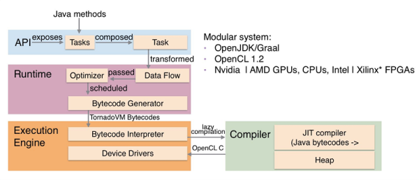
There was a time when running a program on an array of processors meant that you worked in some high-powered lab somewhere. Now your computer probably has plenty of processors hiding in its GPU and if you have an FPGA, you have everything you need to make something custom. The idea behind TornadoVM is to modify OpenJDK and GraalVM to support running some Java code on parallel architectures supported by OpenCL. The system can utilize multi-core CPUs, GPUs (NVIDIA and AMD), Intel integrated GPUs, and Intel FPGAs.
If you want to try your hand at accelerated Java, there are some docker containers to get you started fast. There’ are also quite a few examples, such as a computer vision application.


