Light Emitting Logic Gates Built From Scratch

What’s the weirdest computer you can think of? This one’s weirder.

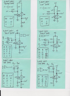
[Dr. Cockroach] figured out a way to create an inverting NOT gate from just one LED and two resistors (one being a photo-resistor). The Dr. has since built AND, NAND, OR, NOR, XOR and XNOR gates, as well as a buffer, incorporating light into every logic gate.

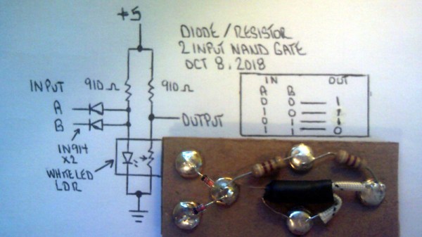
Traditional inverters – NOT gates – are already made with diodes (typically not light-emitting), resistors (typically not light-dependent), and bipolar transistors. The challenge was to reduce the number of transistors. The schematic from the very first test shows the slight modifications [Dr. Cockroach] made to incorporate light into the logic gate using a 910 Ohm, output LED, and an LED and LDR in parallel.

The output is initially 4.5V for logic 1 and 1.5V for logic 0. Adding two 1N914 diodes and an AND gate ahead of the inverter create a two-input NAND gate. With the two diodes reversed and a 910 Ohm resistor removed, a NOR gate is created.

The next step was to build a S-R latch using the NAND gates and inverters, which holds some basic memory. From there, with some size reductions, a Master-Slave J-K Flip Flop, similarly using NAND gates and inverters, can be built. The current state of the project is a working sequencer and counter. You can even see a smooth sine wave propagating through the LED chaser, which is typically built with ICs or transistors but in this case is built simply with LEDs, LDRs, resistors, and capacitors.

The upcoming plan is to use the gates to build a processor that only uses diodes, resistors, and capacitors. While it’s probably not going to be nearly as fast as any processors we have today, it should be interesting (and educational!) to be able to visually track the flow of data from one logic gate over to the next. Continue reading “Light Emitting Logic Gates Built From Scratch”

Shedding A Bit Of Light On Some Logic

When it comes to logic technologies, we like to think we’ve seen them all here at Hackaday. But our community never ceases to surprise us with its variety and ingenuity, so it should be a surprise that [Dr Cockroach] has delivered one we’ve not seen before. Light logic doesn’t use the conventional active devices you’d expect such as transistors, tubes, or even relays. Instead, it uses LEDs and CdS cells to make rudimentary switches. So far there is a NAND, a NOR, and a set-reset latch that appears in the video below the break, and it is not inconceivable that much more complex devices could be crafted.

The CdS cell switch is not too far different in operation to a transistor, with the CdS cell forming half of a potential divider as a rough equivalent of a collector-emitter circuit, and the LED feeding its light to the cell and forming a rough equivalent of a base circuit. It would probably not form a very good analog of a transistor and it seems likely that is will not be the fastest of devices, but we applaud the ingenuity in coming up with it.

CdS cells are a component that seems almost to come from another era, redolent of childhood electronic kits from days of yore. It’s no surprise we don’t see them too often, though, they pop up in the occasional automatic sunglasses.

Continue reading “Shedding A Bit Of Light On Some Logic”

Logic Analyzers: Decoding And Monitoring

Last time, we looked into using a logic analyzer to decode SPI signals of LCD displays, which can help us reuse LCD screens from proprietary systems, or port LCD driver code from one platform to another! If you are to do that, however, you might find a bottleneck – typically, you need to capture a whole bunch of data and then go through it, comparing bytes one by one, which is quite slow. If you have tinkered with Pulseview, you probably have already found an option to export decoded data – all you need to do is right-click on the decoder output and you’ll be presented with a bunch of options to export it. Here’s what you will find:

2521888-2521888 I²C: Address/data: Start
2521896-2521947 I²C: Address/data: Address write: 22
2521947-2521954 I²C: Address/data: Write
2521955-2521962 I²C: Address/data: ACK
2521962-2522020 I²C: Address/data: Data write: 01
2522021-2522028 I²C: Address/data: ACK
2522030-2522030 I²C: Address/data: Start repeat
2522038-2522089 I²C: Address/data: Address read: 22
2522089-2522096 I²C: Address/data: Read
2522096-2522103 I²C: Address/data: ACK
2522104-2522162 I²C: Address/data: Data read: 91
2522162-2522169 I²C: Address/data: NACK
2522172-2522172 I²C: Address/data: Stop

Whether on the screen or in an exported file, the decoder output is not terribly readable – depending on the kind of interface you’re sniffing, be it I2C, UART or SPI, you will get five to ten lines of decoder output for every byte transferred. If you’re getting large amounts of data from your logic analyzer and you want to actually understand what’s happening, this quickly will become a problem – not to mention that scrolling through the Pulseview window is not a comfortable experience.

The above output could look like this: 0x22: read 0x01 ( DEV_ID) = 0x91 (0b10010001). Yet, it doesn’t, and I want to show you how to correct this injustice. Today, we supercharge Pulseview with a few external scripts, and I’ll show you how to transfer large amounts of Sigrok decoder output data into beautiful human-readable transaction printouts. While we’re at it, let’s also check out commandline sigrok, avoiding the Pulseview UI altogether – with sigrok-cli, you can easily create a lightweight program that runs in the background and saves all captured data into a text file, or shows it on a screen in realtime! Continue reading “Logic Analyzers: Decoding And Monitoring”

Modern Microcontroller Boosts Classic Logic Analyzer To New Heights

[Ted Fried] recently found a beautiful HP 1600A/1607A logic analyzer set. State of the art in 1975, it looks like glorious Space Age equipment today. He decided to hook it up some modern gear to put it through its paces.

Wanting to give the equipment a proper shakedown, he enlisted a Teensy 4.1 to spit a deluge of logic at the HP unit. The microcontroller was tasked with generating 32 data signals along with two clock outputs to give the analyzer plenty to analyze. The HP 1600A handled this no problem, so [Ted] kept tinkering.

His next feat was to explore the addressable “MAP” function of the unit, which allowed writing to the 64×64 pixel display. The Teensy 4.1 was easily able to send images to the display, but [Ted] isn’t stopping there. He’s got plans to do the usual thing and get Bad Apple going on the hardware.

Getting a logic analyzer to analyze logic isn’t much of a hack, sure. But it’s instructive of how to approach working with such hardware. If you want to spit a bunch of logic out fast, a Teensy 4.1 is a great choice because it’s got a ton of IO and a ton of clock cycles to tickle it with.

We enjoyed seeing this old piece of hardware light up the phosphors once more. If you’ve got your own projects going on with classic bits of HP test gear, don’t hesitate to let us know!

Light Guns Aren’t Just For CRTs Anymore

For how much of a cultural phenomenon light gun games like Duck Hunt were, they didn’t survive the transition from CRT televisions to LCDs particularly well because of all of the technological quirks the light guns exploited in older technology that simply disappeared with modern TVs. But it’s not impossible to get a similar gameplay from modern technology as evidenced by the success of the Wii and its revolutionary Wiimote, and there are plenty of modern games that use similar devices. There are a few paths to getting older light guns working again, though.

The first system to note, called SAMCO, uses a system of LEDs and a camera to synchronize the game’s flashes to the new technology and translate the input back into the game. Gun4ir uses a similar technique, and boasts extremely high accuracy and low latency largely due to being programmed in assembly. Both systems can use either an infrared tracking sensor or a Wiimote sensor as the LEDs and while the SAMCO system can run on a Raspberry Pi Pico, Gun4ir exclusively uses ATmega32U4 boards with the optimized assembly programming.

Both SAMCO and Gun4ir offer PCBs for anyone looking to try them out without designing their own circuit boards, and once the electronics are assembled they can either be put in an original NES-era light gun, put in a custom printed enclosure, or even stuffed into a Nerf gun. For others looking for a more turnkey solution, there are also offerings from companies like Sinden which make complete system. You can always build your own system to restore the functionality of original light guns from scratch if that’s more your style.

Thanks to [LookAtDaShinyShiny] for tipping us off to the latest happenings in the light gun community!

Photo courtesy of Wikimedia Commons

Using 5V Programmable Logic Here In The 2020s

Do you speak GAL? [Peterzieba] does, and has pulled together a collection of documents and tools so that you can too. There’s a dividing line in electronic engineering education, between those who were taught about FPGAs, and those who weren’t. Blurring that line slightly is gate array logic (GAL). These devices were a preceursor to the FPGA, with a much simpler structure, and usually in those days UV-erasable in the same manner as an EPROM. And oddly enough, they, or at least their successor compatible parts, are still available, and as handy DIP devices that talk to 5 volt logic.

The guide goes into detail about the parts, the terminology surrounding them, and the CUPL language which raises a few memories for us. There are several possible workflows, including for those not faint of heart, the possibility of writing a fusemap by hand. We’re impressed by that one.

If these devices interest you, our colleague Bil Herd wrote a two-part guide (part one, and part two) which should answer your questions.

Thanks [Bjonnh] for the tip!

Featured image: “Commodore Amiga 1000 – sub board – Texas Instruments PAL16L8ACN-0126” by Raimond Spekking

Logic Analyzers: Capabilities And Limitations

Last time, we’ve used a logic analyzer to investigate the ID_SD and ID_SC pins on a Raspberry Pi, which turned out to be regular I2C, and then we hacked hotplug into the Raspberry Pi camera code with an external MCU. Such an exercise makes logic analyzers look easy, and that’s because they are! If you have a logic analyzer, you’ll find that a whole bunch of hacks become available to you.

In this article, let’s figure out places where you can use a logic analyzer, and places where you can’t. We’ll start with the first limitation of logic analyzers – capture speed. For instance, here’s a cool thing you can buy on Aliexpress – a wristband from TTGO that looks like a usual fitness tracker, but has an ESP32 in it, together with an IMU, an RTC, and an IPS screen! The seller also has an FFC-connectable devboard for programming this wristband over UART, plus vibromotor and heartrate sensor expansion modules.

You can run C, MicroPython, Rust, JavaScript, or whatever else – just remember to bring your own power saving, because the battery is super small. I intended to run MicroPython on it, however, and have stumbled upon a problem – the ST7735-controller display just wouldn’t work with the st7735.py library I found; my image would be misaligned and inverted.

The specifications didn’t provide much other than “ST7735, 80×160”. Recap – the original code uses an Arduino (C++) ST7735 library and works well, and we have a MicroPython ST7735 library that doesn’t. In addition to that, I was having trouble getting a generic Arduino ST7735 library to work, too. Usually, such a problem is caused by the initialization commands being slightly different, and the reason for that is simple – ST7735 is just the name of the controller IC used on the LCD panel.

Each display in existence has specifics that go beyond the controller – the pixels of the panel could be wired up to the controller in a bunch of different ways, with varying offsets and connection types, and the panel might need different LCD charge pump requirements – say, depending on the panel’s properties, you might need to write 0x10 into a certain register of the ST7735, or you will need 0x40. Get one or more of these registers wrong, and you’ll end up with a misaligned image on your display at best, or no output at worst. Continue reading “Logic Analyzers: Capabilities And Limitations”