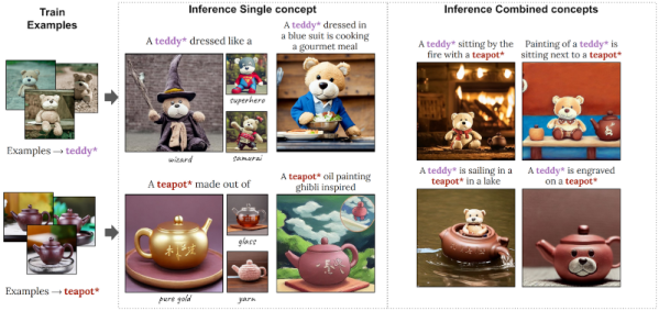
Running your own AI models is possible, but it requires a giant computer, right? Maybe not. Researchers at NVidia are showing off Perfusion, a text-to-image model they say is 100KB in size and takes four minutes to train. The model specializes in customizing a photo. For example, the paper shows a picture of a teddy bear and a prompt to dress it as a wizard. In all fairness, the small size and quick training are a little misleading, we think, because the results are still using the usual giant model. What’s small and fast is the customization of the existing model.
Customizing models is a common task since you often want to work with something the model doesn’t contain. For example, you might want to alter a picture of your face or your pet, which probably isn’t in the original model. You can create a special keyword and partially train the model for what you want using something called textual inversion. The problem the researchers identified is that creating textual inversions often causes the new training to leak to unintended areas.
They describe “key locking,” a technique to avoid overfitting when fine-tuning an existing model. For example, suppose you want to add a specific dog picture to the model. With typical techniques, a special keyword like dog* will indicate the custom dog image, but the keyword has no connection with generic dogs, mammals, or animals. This makes it difficult for the AI to work with the image. For example, the prompts “a man sitting” and “a dog sitting” require very different image generations. But if we train a specific dog as “dog*” there’s no deeper understanding that “dog*” is a type of “dog” that the model already knows about. So what do you do with “dog* sitting?” Key locking makes that association.