Optical Centrepunch Is An Easy Build If You Need One

Tired of getting his centerpunches thereabouts but not quite there, [Uri] decided something had to be done. A common tool to solve this problem is the optical centerpunch, but models on sale were just a little too pricy for something so basic. Instead, [Uri] elected to build his own.

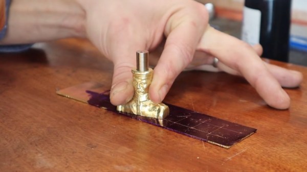
An optical centerpunch is a simple tool that helps machinists hit a centerpunch dead on target, time after time. A guide is used that holds a clear plastic rod with a dot in the center. This dot is lined up over the spot to be centerpunched. The plastic rod is then removed and replaced with the actual punch that does the work. Not content to build something utilitarian, [Uri] instead sculpted the tool into a likeness of Sgt Pepper (of Yellow Submarine fame). Seeing the hunk of bare brass quickly become a recognisable figure on camera is a testament to [Uri’s] skill as a sculptor.

It’s a tool that can be readily built by anyone with a lathe, or, at the very least, a decent drill press. We imagine it would be particularly useful for those without perfect vision, making it easier to get punches on the mark on a regular basis. [Uri] has graced these pages before, too — he previously built an ornate tool to make all the other hammers jealous. Video after the break.

Continue reading “Optical Centrepunch Is An Easy Build If You Need One”

Get Over Your Fears

Some projects are just too complex, that’s for sure. But I’d be willing to bet that some things you think are too difficult actually aren’t, and it may be that all you need to get over your personal hurdle is a good demonstration. Here come three cases in point.

I was looking at the new Raspberry Pi Compute Module last weekend. They have a whole bunch of high-speed traces: things like Gigabit Ethernet, HDMI, and those crazy-fast SDI serial camera interfaces. I have no experience in high-speed design and layout at all, and frankly it gives me the willies. But the Raspberries also shipped me an IO demo board, and concomitant KiCAD design files, with the review board. Looking at it, they were just wires — maybe pairwise length-matched and impedance controlled — but also just wires. Opening up the KiCAD board file and clicking on the traces just like I do with my own designs, I’m a lot less scared. That was a revelation for me.

In a great writeup of his experience building ten different Linux single-board-computers from scratch, Jay Carlson had a similar effect on me. I would never have considered breaking out the hotplate for some CPU-and-DRAM action, and I’ve never had to lay out a PCB with a high density BGA chip before either. I’m not quite into Dunning-Kruger territory yet; I still have a healthy respect for the layout intricacies in fanning out a tight BGA CPU into a DRAM. But Jay’s frank assessments of what is easy and what is hard make it all seem within the realm of the doable.

As Mike and I were talking on the podcast about Jay’s work, Mike came clean about his fear of BGAs. I’ve done enough reflow-plate soldering, with parts that have a lead pitch that’s a factor of two finer than the 0.8 mm pitch BGAs in question, so it doesn’t seem implausible to me. And I’m 100% sure Mike could pull it off too, but he is in need of a BGA guru. Any good hobbyist videos out there?

Being a nerdy type, I’m much more focused on the knowledge and the inspiration, but maybe the courage is equally important — at least I think I undervalue it. I don’t need to lay out HDMI lines, or build a from-scratch Linux box, but I am no longer afraid that I couldn’t, and that’s because I’ve seen detailed examples of fellow hackers who’ve done the same. I might not get it right on the first shot, but I’m not afraid to try, and I wouldn’t have said the same before looking over other folks’ shoulders. Forza e corragio!

Super-Simple VGA Adapter Sports Low-Res Output With Only Four TTL Chips

Here at Hackaday we cast a wary eye at tips that come in with superlative claims. Generally, if we post something that claims to be the fastest or the smallest of all time, we immediately get slapped down in the comments by someone who has done it faster or smaller. So we present the simplest TTL video card ever knowing the same thing will happen, but eager to see how anyone might scale things down.

To be fair, [George Foot] does qualify his claim to the simplest usable VGA adapter, and he does note that it descends from [Ben Eater]’s “world’s worst video card”, which he uses for his 6502 breadboard computer. But where [Ben]’s VGA adapter uses about 20 TTL chips and an EEPROM, [George] has managed to decrease the BOM to just four TTL chips along with the memory and a crystal oscillator. This required a fair number of compromises, of course; the color depth is fairly low, as is the resolution. Each pixel appears as a thin horizontal bar rather than a small square, leading the images to be smeared out across the screen. They’re still surprisingly viewable, though, which probably says more about the quality of the pattern-recognition wetware between our ears than anything about the quality of the adapter. [George] gives a tour of the circuit in the brief video below.

It looks like [George] has posted a few improvements to the project since we first spotted it, so we’re looking forward to seeing how much the parts count went up. We’re also keen to see if anyone can outdo the simplicity of this effort — be sure to let us know if you give it a shot.

Continue reading “Super-Simple VGA Adapter Sports Low-Res Output With Only Four TTL Chips”

Proprietary Lenses Are No Problem With This USB Adaptor

There was a time when a camera lens was simply a set of shaped pieces of glass in a tube, with a mount and an aperture. But as cameras have embraced electronics ever more, technology has found its way past the lens mount to the extent that all features of a modern lens are electronically controllable. Can they be used outside the confines of the camera they were designed for? If the user is [Jana Marie] then certainly, because she’s created a nifty USB adapter and mount for Canon lenses for use with her custom streaming camera.

The hardware is a 3D printed lens mount with a PCB that mates with the pins on the lens. An STM32 does the hard work and talks to the outside world through a USB interface, however it’s in the software that the real effort lies. The Canon lens protocol has been extended since the 1980s, and the commands for different generations of lenses can be convoluted. All the information is in a GitHub repository, so the curious hacker can roll their own.

There are a wealth of camera projects to be found for those that don’t mind tearing apart some of their more valuable possessions, and this isn’t the first we’ve seen involving the hacking of the Canon protocol.

Relay Computer Consumes Six Years And 4.5 Suitcases

If you thought your home-brew project was taking a long time, [Jeroen Brinkman]’s MERCIA Relay Computer project probably has you beat. He began working on this impressive computer back in 2014, and has been at it ever since.  In fact, the ongoing nature of the project is embedded into the name itself — the English translation of the acronym MERCIA is “My Simple Relay Computer Under Construction”.  Being interested in old analog and relay computers from an early age, [Jeroen] took on this project to educate students about how computers work.  The entire computer is build only using relays, diodes, and capacitors, not to mention color-coded wire based on signal functions. Using relays as the primary switching elements is at the core of his educational goal — anyone can understand how a relay works.

Understandably, this thing is big.  But he has cleverly packaged it to visually show the major building blocks of a computer.  While the exact size isn’t stated, we can estimate based on the photo of [Jeroen] standing next to the modules that these panels are about 1.5 m tall and perhaps 60 cm wide.  The whole computer is nine panels wide, making it about 5 meters long.  Except for the ROM assembly, pairs of panels are hinged together and they fold like a book and carried like a suitcases when being moved.  If you enjoy the clickety-clack sound of relays, be sure to watch the relay longevity test in the video below and check out our article on the 1958 FACOM from last year.

This is a fascinating project, but unless you have a couple thousand relays laying around and a decade of free time, it’s probably better to just enjoy [Jeroen]’s work rather than build your own.  We hope he releases schematics and other documentation once the project is finished.  You can follow his Facebook build log if you want to keep track of the progress. Thanks to [David Gustafik] for the tip.

Continue reading “Relay Computer Consumes Six Years And 4.5 Suitcases”

Short Video Recaps A Long Tradition Of Space Hacks

Human spaceflight has always been, and still remains, a risky endeavor. We mitigate risk by being as prepared as we can. Every activity is planned, reviewed, and practiced long before any rocket engines are ignited. But space has a history of not cooperating with plans, and thus there is a corresponding history of hacks to get missions back on track. YouTube space fan [Scott Manley] recaps some of his favorites in How a $2 Toothbrush Saved the ISS and Other Unbelievable Space Hacks.

The introduction explained this compilation was motivated by the latest International Space Station drama, where an elusive air leak has finally been tracked down. Air leaks are obviously much more worrying in a space station than in, say, a bicycle tire. Thus there exists a wide array of tools to track down leaks but they couldn’t find this one. Reportedly the breakthrough came from an improvised airflow visualization tool: leaves from a cut-open tea bag. Normally small floating particles are forbidden in space because they might end up in troublesome places. (Eyes, noses, onboard equipment…) Apparently the necessity of the hack outweighed the rules here.

Tea leaves are but the latest in a long line of hacks devised in the course of space missions, because things don’t always go according to the original plan. Or even any of the large volume of contingency plans. Solutions have to be cobbled together from resources on hand, because when we’re in space, what we brought is all we have. From directly editing production code during Apollo 14, to a field-built replacement fender for the Apollo 17 Lunar Rover Vehicle (top picture), to the $2 toothbrush pressed into service as metal debris cleaner. The mission must go on!

Continue reading “Short Video Recaps A Long Tradition Of Space Hacks”

A Plethora Of Power Delivery Potential

Here at the Hackaday we’ve been enjoying a peculiar side effect of the single-port USB-C world; the increasing availability of programmable DC power supplies in the form of ubiquitous laptop charging bricks. Once the sole domain of barrel jacks or strange rectangular plugs (we’re looking at you Lenovo) it’s become quite common to provide charging via the lingua franca of USB-C Power Delivery. But harnessing those delectable 100W power supplies is all to often the domain of the custom PCBA and firmware hack. What of the power-hungry hacker who wants to integrate Power Delivery in her project? For that we turn to an excellent video by [Brian Lough] describing four common controller ICs and why you might choose one for your next project.

A superb illustration from the TS100 Flex-C-Friend documentation

[Brian] starts off with a sorely-needed explainer of what the heck Power Delivery is; a topic with an unfortunate amount of depth. But the main goal of the video is to dive into the inscrutable hoard of “USB C trigger boards.” Typically these take USB on one side and provide a terminal block on the other, possibly with a button or LED as user interface to select voltage and current. We’ve seen these before as laptop barrel jack replacements and TS100 power supplies but it’s hard to tell which of the seemingly-identical selection is most suitable for a project.

The main body of the video is [Brian’s] detailed walkthrough of four types of trigger boards, based on the IP2721, FUSB302, STUSB4500, and Cypress EZ-PD BCR. For each he describes the behaviors of it’s particular IC and how to configure it. His focus is on building a board to power a TS100 (which parallels his TS100 Flex-C-Friend) but the content is generally applicable. Of course we also appreciate his overview of the products on Tindie for each described module.

For another angle on Power Delivery, check out this series of posts by [jason cerudolo], a perennial favorite. And don’t miss his classic project, the USB Easy Bake Oven.