Modified 3D-Printer Solders Through-Hole Components

Surface-mount technology has been a fantastic force multiplier for electronics in general and for hobbyists in particular. But sometimes you’ve got no choice but to use through-hole components, meaning that even if you can take advantage of SMDs for most of the design, you still might need to spend a little time with soldering iron in hand. Or not, if you’ve got a spare 3D printer lying around.

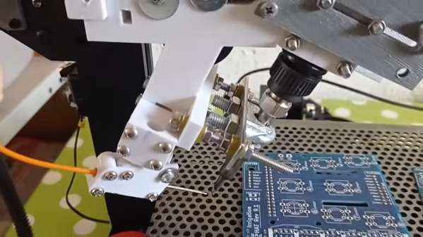
All we’ve got here is a fairly brief video from [hydrosys4], so there aren’t a lot of build details. But it’s pretty clear what’s going on here. Starting with what looks like a Longer LK4 printer, [hydrosys4] added a bracket to hold a soldering iron, and a guide for solder wire. The solder is handled by a more-or-less standard extruder, which feeds it into the joint once it’s heated by the iron. The secret sauce here is probably the fixturing, with 3D-printed jigs that hold the through-hole connectors in a pins-up orientation on the bed of the printer. With the PCB sitting on top of the connectors, it’s just a matter of teaching the X-Y-Z position of each joint, applying heat, and advancing the solder with the extruder.

The video below shows it in action at high speed; we slowed it down to 25% to get an idea of how it is in reality, and while it might not be fast, it’s precise and it doesn’t get tired. It may not have much application for one-off boards, but if you’re manufacturing small PCB runs, it’s a genius solution. We’ve seen similar solder bots before, but hats off to [hydrosys4] for keeping this one simple.

Continue reading “Modified 3D-Printer Solders Through-Hole Components”
Magnetic Bearings Put The Spin On This Flywheel Battery

[Tom Stanton] is right about one thing: flywheels make excellent playthings. Whether watching a spinning top that never seems to slow down, or feeling the weird forces a gyroscope exerts, spinning things are oddly satisfying. And putting a flywheel to work as a battery makes it even cooler.

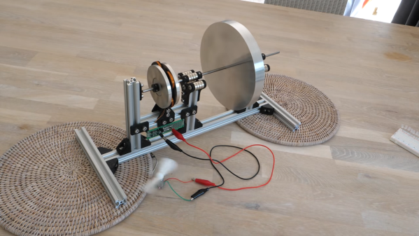
Of course, using a flywheel to store energy isn’t even close to being a new concept. But the principles [Tom] demonstrates in the video below, including the advantages of magnetically levitated bearings, are pretty cool to see all in one place. The flywheel itself is just a heavy aluminum disc on a shaft, with a pair of bearings on each side made of stacks of neodymium magnets. An additional low-friction thrust bearing at the end of the shaft keeps the systems suitably constrained, and allows the flywheel to spin for twelve minutes or more.

[Tom]’s next step was to harness some of the flywheel’s angular momentum to make electricity. He built a pair of rotors carrying more magnets, with a stator of custom-wound coils sandwiched between. A full-wave bridge rectifier and a capacitor complete the circuit and allow the flywheel to power a bunch of LEDs or even a small motor. The whole thing is nicely built and looks like a fun desk toy.

This is far from [Tom]’s first flywheel rodeo; his last foray into storing mechanical energy wasn’t terribly successful, but he has succeeded in making flywheels fly, one way or another.

Continue reading “Magnetic Bearings Put The Spin On This Flywheel Battery”

Raspberry Pi Server Cluster In 1U Rack-Mount Case

[Paul Brown] wants to take advantage of off-site server colocation services. But the providers within [Paul]’s region typically place a limit of 1A @ 120V on each server. Rather than search out commercial low-power solutions, [Paul] embraced the hacker spirit and built his own server from five Raspberry Pi 4b single board computers.

The task involves a little bit more than just mounting five Pi4s in a chassis and calling it done. There is an Ethernet switch connecting all the modules to the network, and each Pi has a comparatively bulky SSD drive + enclosure attached. By far the most annoying part of the assembly is the power supply and distribution cabling, which is further complicated by remote controlled power switching relays (one of the computers is dedicated to power management and can shut the other four modules on and off).

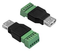
Even if you’re not planning on building your own server, check out the thoroughly documented assembly process and parts list — we particularly liked the USB connector to screw terminal breakout connector that he’s using for power distribution. For all the detailed information, assembly instructions and photos, we think a top-level block diagram / interconnection drawing would be very helpful for anyone trying to understand or replicate this project.

There are a lot of connections in this box, and the final result has a messy look-and-feel. But in fairness to [Paul]’s craftsmanship, there aren’t many other ways to hook everything together given the Raspberry Pi form-factor. Maybe a large and costly PCB or using CM4 modules instead of Raspberry Pi boards could help with cable management? In the end, [Paul] reckons he shelled out about $800 for this unit. He compares this expense with some commercial options in his writeup, which shows there are some cheaper and more powerful solutions. But while it may be cheaper to buy, we understand that strong urge to roll your own.

We’ve written about many Pi cluster projects in the past, including this one which contains a whopping 750 Raspberry Pis. Have you ever used a colocation service, and if so, did you use a DIY or an off-the-shelf server?

Miller (Effect) Time

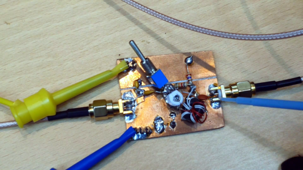
While the Miller effect might sound like fun, it is actually the effect of parasitic capacitance in amplifiers. What do you do about it? Watch the video below the break from [All Electronics] and find out. We like how the test circuit it uses has a switch to put the mitigation circuitry in and out of the test for comparison purposes.

Actually, the Miller effect can refer to any impedance but in practice that is most often parasitic capacitance because of the construction used for tubes and transistors. The sometimes tiny capacitance gets multiplied by the inverting gain of the stage and increases the amplifier’s input impedance. This, in turn, reduces the bandwidth of the stage.

Continue reading “Miller (Effect) Time”

salah_360display-photos

A New Spin On 360 Degree Displays

Back in 2018, [Salah] created a prototype display that seems to defy logic using little more than a Pringles can and a fast motor. While not volumetric, this hack does show the same 2D image from any vantage point in 360 degrees around it.

How can cardboard create this effect? Somewhat like a zoetrope uses slits to create a shutter effect, this display uses a thin slit to limit the view of the image within to one narrow vertical slice at a time. When moving fast enough, Persistence of Vision kicks in to assemble these slices into a complete image. What we think is so cool about this hack is that the effect is the same from any angle and by multiple viewers simultaneously.

The project page and video demonstration after the break are light on details, though the idea is so simple as to not require additional explanation. We assume the bright LED seen in the video below was added to overcome the relatively dim appearance of the image when viewed through the narrow slit and isn’t strictly required.

Continue reading “A New Spin On 360 Degree Displays”

Clever PCB Brings Micro USB To The Arduino Uno

Even with more and more devices making the leap to USB-C, the Arduino Uno still proudly sports a comparatively ancient Type-B port. It wouldn’t be a stretch to say that many Hackaday readers only keep one of these cables around because they’ve still got an Uno or two they need to plug in occasionally.

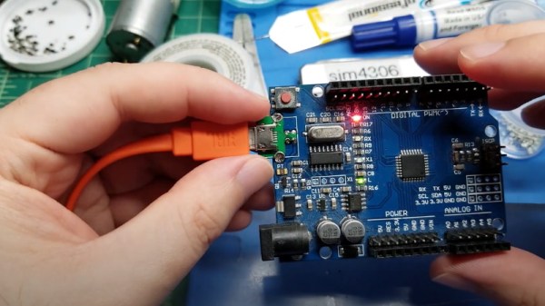
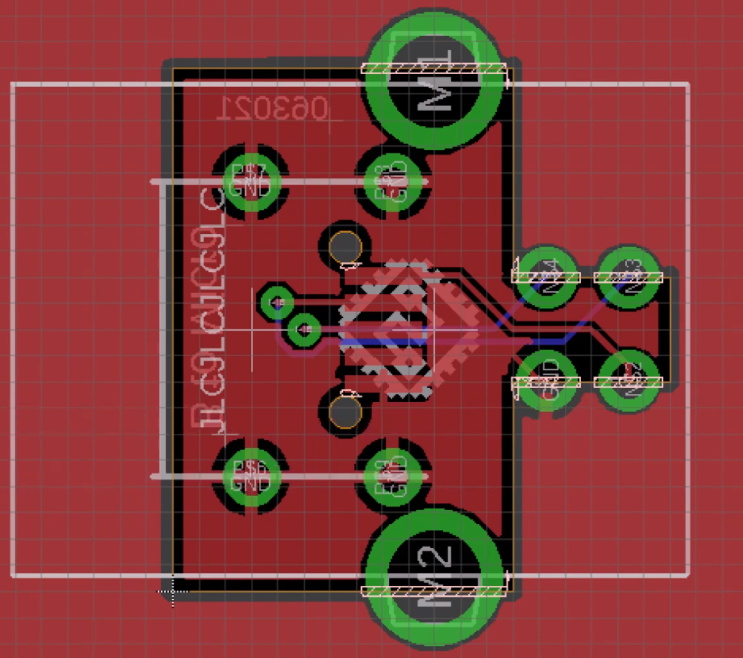
Looking to at least move things in the right direction, [sjm4306] recently set out to create a simple board that would let him mount a micro USB connector in place of the Uno’s original Type-B. Naturally there are no components on the PCB, it simply adapts the original through-hole footprint to the tight grouping of surface mount pads necessary to mount a female micro USB port.

Making castellated holes on the cheap.

The design is straightforward, but as [sjm4306] explains in the video below, there’s actually more going on here than you might think. Looking to avoid the premium he’d pay to have the board house do castellated holes, he cheated the system a bit by having the board outline go right through the center of the standard pads.

Under a microscope, you can see the downside of this approach. Some of the holes got pretty tore up as the bit routed out the edges of the board, with a few of them so bad [sjm4306] mentions there might not be enough of the pad left to actually use. But while they may not be terribly attractive, most of them were serviceable. To be safe, he says anyone looking to use his trick with their own designs should order more boards than they think they’ll actually need.

Of course you could go all the way and retrofit the Uno with a USB-C port, as we’ve seen done with devices in the past. But the latest-and-greatest USB interface can be a bit fiddly, especially with DIY gadgets, so we can’t blame him for going with the more reliable approach.

Continue reading “Clever PCB Brings Micro USB To The Arduino Uno”

ZeroBug: From Simulation To Smooth Walking

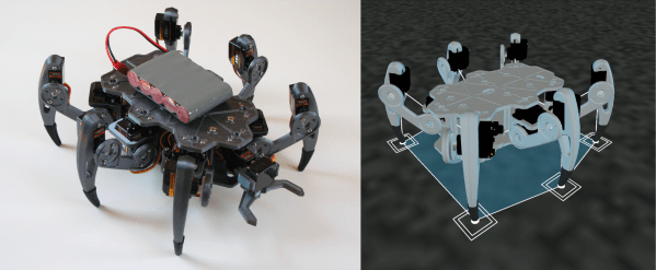
Thanks to 3D printing and cheap hobby servos, building you’re own small walking robot is not particularly difficult, but getting them to walk smoothly can be an entirely different story. Knowing this from experience, [Max.K] tackled the software side first by creating a virtual simulation of his ZeroBug hexapod, before building it.

Learning from his previous experience building a quadruped, ZeroBug started life in Processing as a simple stick figure, which gradually increased in complexity as [Max.K] figured out how to make it walk properly. He first developed the required movement sequence for the tip of each leg, and then added joints and calculated the actuator movements using reverse kinematics. Using the results of the simulations, he designed the mechanics and pulled it back into the simulation for final validation.

Each leg uses three micro servos which are controlled by an STM32F103 on a custom PCB, which handles all the motion calculations. It receives commands over UART from a python script running on a Raspberry Pi Zero. This allows for user control over a web interface using WiFi, or from a gamepad using a Bluetooth connection. [Max.K] also added a pincer to the front to allow it to interact with its environment. Video after the break.

The final product moves a lot smoother than most other servo-driven hexapods we’ve seen, and the entire project is well documented. The electronics and software are available on GitHub and the mechanics on Thingiverse.

Continue reading “ZeroBug: From Simulation To Smooth Walking”