TI-99/4A KSP Controller Has A Handle On Vintage NASA Styling

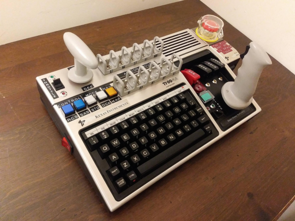
[MelkorsGreatestHits] had an extra USB MAME board burning a hole in his parts bin, so he turned it into fuel for this far-out Kerbal Space Program controller. Cool your jets — no fully-functioning TI-99/4As were harmed in the making of this baby. Besides, this is a KAL 9000 from Kexas Instruments. See the badges?

After donating the usable parts deemed unnecessary for space exploration, [MelkorsGreatestHits] had even more room inside the case for the throng of toggles that make this controller so touchable. We love the two tiers of toggles here — the important ones are separated with 3D-printed Space Shuttle-style switch guards, and the super-important toggles have flip-up covers to protect them from errant flicks of the hand. The vintage embosser labels are an impressive touch, and make us wish we had one that stamps vertically.

[MelkorsGreatestHits] modeled the combo throttle/roll handle and the joystick after the Apollo 11 command module controls. Unfortunately, the MAME board didn’t like his 3-axis analog joystick, so both are 2-axis and give WASD control. Good enough to get to the Mün!

We’ve seen more than a few KSP controllers around here, but none so overdone as this wonderful stand-up command station.

Via r/DIY

A Visual Infrared Thermometer That Runs Off Your Laptop

A common measurement for circuits is heat dissipation inspection. While single point thermometers do the trick, they can be quite annoying to use. Meanwhile, a thermal imaging camera is often out of the budget for hobbyists. How about building your own visual thermometer for cheap? That’s what [Thomas Fischl] decided to do, using an infrared thermal sensor array (MLX90640) connected through a PIC16LF1455 to a host computer. The computer handles the temperature calculation and visualization of hot spots, gathered from data collected by the IR pixel.

The interface board, USB2FIR, has full access to MLX90640 memory and can handle bulk transfer for faster data transmission of the raw sensor data collected by the pixel. A USB driver is needed to access the board – once the data is fetched, the visualizations can be created from a Matplotlib and TKinter GUI showing frame data and a real time heat map with minimum, maximum, and central temperature.

The hardware isn’t complicated, since the board relies on several ICs for processing the sensor data and immediately sends over the data to be processed externally. With some modifications – a 3D-printed enclosure, for instance – this can easily be made into a discreet tool for heat detection.

Faux Cow Munches Faux Grass On A Faux Roomba

Out in the countryside, having a cow or to two wouldn’t be a big deal. You can have a cattle shed full of them, and no one will bat an eyelid. But what if you’re living in the big city and have no need of pet dogs or cats, but a pet cow. It wouldn’t be easy getting it to ride in the elevator, and you’d have a high chance of being very, very unpopular in the neighbourhood. [Dane & Nicole], aka [8 Bits and a Byte] were undaunted though, and built the Moomba – the Cow Roomba to keep them company in their small city apartment.

The main platform is built from a few pieces of lumber and since it needs to look like a Roomba, cut in a circular shape. Locomotion comes from two DC geared motors, and a third swivel free wheel, all attached directly to the wooden frame. The motors get their 12V juice from eight “AA” batteries. The free range bovine also needs some smarts to allow it to roam at will. For this, it uses a Raspberry Pi powered by a power bank. The Pi drives a 2-channel relay board which controls the voltage applied to the two motors. Unfortunately, this prevents the Moomba from backing out if it gets stuck at a dead end. For anyone else trying to build this it should be easy enough to fix with an electronic speed controller or even by adding a second 2-channel relay board which can reverse the voltage applied to the motors. The Moomba needs to “Moo” when it feels like, so the Raspberry Pi streams a prerecorded mp3 audio clip to a pair of USB speakers.

If you see the video after the break, you’ll notice that making the Moomba sentient is a simple matter of doing “ctrl+C” and “ctrl+V” and you’re good to go. The python code is straight forward, doing one of four actions – move forward, turn left, turn right or play audio. The code picks a random number from 0 to 3, and then performs the action associated with that number. Finally, as an added bonus, the Moomba gets a lush carpet of artificial green grass and it’s free to roam the range.

At first sight, many may quip “where’s the hack” ? But simple, easy to execute projects like these are ideal for getting younglings started down the path to hacking, with adult supervision. The final result may appear frivolous, but it’ll excite young minds as they learn from watching.

Continue reading “Faux Cow Munches Faux Grass On A Faux Roomba”

Reverse-Engineering Xiaomi IoT Firmware

IoT devices rarely ever just do what they’re advertised. They’ll almost always take up more space than they need to – on top of that, their processor and memory alone should be enough to run a multitude of other tasks while not necessarily compromising the task they were built to do.

That’s partially the motivation for rooting any device, but for Xiaomi devices, it’s a bit more fun – that is to say, it’s a little bit harder when you’re reverse engineering its firmware from scratch.

Similar to his other DEF CON 26 talk on modifying ARM Cortex-M firmware, [Dennis Giese] returns with a walkthrough of how to reverse-engineer Xiaomi IoT devices. He starts off talking about the Xiaomi ecosystem and the drawbacks of reusing firmware across all the different devices connected to the same cloud network before jumping into the walkthrough for accessing the devices.

Continue reading “Reverse-Engineering Xiaomi IoT Firmware”

Wiping Your Windscreen To The Beat

Nothing spoils your mood quite like your windscreen wipers not feeling it when the beat drops. Every major car manufacturer is focused on trying to build the electric self driving vehicle for the masses, yet ignoring this very real problem. Well [Ian Charnas] is taking charge, and has successfully slaved his car’s wipers to beat of its stereo.

Starting with the basics, [Ian] first needed to control the speed of the wiper motor. This was done using a custom power supply adapted from another project. The brain of the system is a Raspberry Pi 3B+ which runs a phase locked loop algorithm to sync the music and the motor. Detecting the beat turned out to be the most difficult part of the project, and from the research [Ian] did, there is no standard solution. He ended up settling on “madmom“, a Python audio and music signal processing library, which runs a neural net to detect the beat in real time. The Raspi sends the required PWM and Enable signals to an Arduino over serial, which in turn controls the power supply. The entire system was neatly integrated in the car, with a switch in the dash that connects the motor to the new power supply on demand, to allow the wipers to still be used normally (and safely).

[Ian] filed a provisional patent application for the idea, and will be putting it on auction on eBay soon, with the hope that some major car manufacturer would be interested. For older cars, you can shove an Arduino into the stereo, or do a super cheap bluetooth upgrade. Check out the video after the break. Continue reading “Wiping Your Windscreen To The Beat”

ESP8266 Unlocks Hidden Features In Sound Bar

It’s no secret that the hardware devices we buy are often more capable than their manufacturer leads on. Features hidden behind firmware locks are a common trick, as it allows companies to sell the same piece of gear as a different model by turning off certain capabilities. Luckily for us, these types of arbitrary limitations are often easy to circumvent.

As a perfect example, [Acuario] recently discovered that the LG SJ2 sound bar has quite a few features that aren’t advertised on the box. Whether it’s due to greed or just laziness, it turns out LG isn’t using many of the capabilities offered by the ESMT AD83586B IC inside the amplifier. The chip gets its configuration via I2C, so thanks to the addition of an ESP8266, the expanded capabilities can now be easily enabled through a web interface.

[Acuario] has already found out how to turn on things like simulated surround sound, or per-channel volume controls; all functions which aren’t even exposed through the normal controls on the sound bar. But it goes deeper than that. The LG SJ2 is a 2.1 channel system, with a wireless speaker providing the right and left channels. But the AD83586B inside the subwoofer is actually capable of driving two locally connected speakers, though you obviously need to do a little rewiring.

There are still even more capabilities to unlock, though [Acuario] is currently struggling with some incomplete documentation. The datasheet says there’s support for user-defined equalizer settings, but no examples are given for how to actually do it. If anyone’s got a particular affinity for these sort of amplifier chips, now could be your time to shine.

For hackers, there’s perhaps no better example of feature-locked products than Rigol’s line of oscilloscopes. From the 2000 series of scopes in 2013 up to their higher-end MSO5000 just last year, there’s a long history of unlocking hidden features on these popular tools.

Light Emitting Logic Gates Built From Scratch

What’s the weirdest computer you can think of? This one’s weirder.

[Dr. Cockroach] figured out a way to create an inverting NOT gate from just one LED and two resistors (one being a photo-resistor). The Dr. has since built AND, NAND, OR, NOR, XOR and XNOR gates, as well as a buffer, incorporating light into every logic gate.

Traditional inverters – NOT gates – are already made with diodes (typically not light-emitting), resistors (typically not light-dependent), and bipolar transistors. The challenge was to reduce the number of transistors. The schematic from the very first test shows the slight modifications [Dr. Cockroach] made to incorporate light into the logic gate using a 910 Ohm, output LED, and an LED and LDR in parallel.

The output is initially 4.5V for logic 1 and 1.5V for logic 0. Adding two 1N914 diodes and an AND gate ahead of the inverter create a two-input NAND gate. With the two diodes reversed and a 910 Ohm resistor removed, a NOR gate is created.

The next step was to build a S-R latch using the NAND gates and inverters, which holds some basic memory. From there, with some size reductions, a Master-Slave J-K Flip Flop, similarly using NAND gates and inverters, can be built. The current state of the project is a working sequencer and counter. You can even see a smooth sine wave propagating through the LED chaser, which is typically built with ICs or transistors but in this case is built simply with LEDs, LDRs, resistors, and capacitors.

The upcoming plan is to use the gates to build a processor that only uses diodes, resistors, and capacitors. While it’s probably not going to be nearly as fast as any processors we have today, it should be interesting (and educational!) to be able to visually track the flow of data from one logic gate over to the next. Continue reading “Light Emitting Logic Gates Built From Scratch”