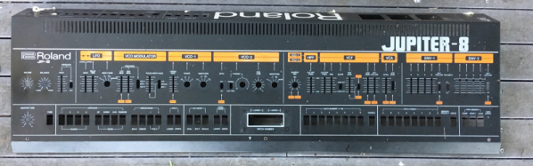
SegaPi Zero Shows Game Gear Some Respect

If you were a gamer in 1991, you were presented with what seemed like an easy enough choice: you could get a Nintendo Game Boy, the gray brick with a slightly nauseating green-tinted screen that was already a couple of years old, or you could get yourself a glorious new Sega Game Gear. With full color display and games that were ported straight from Sega’s home consoles, it seemed like the Game Gear was the true future of portable gaming. But of course, that’s not how things actually went. In reality, technical issues like abysmal battery life held the Game Gear back, and conversely Nintendo and their partners were able to squeeze so much entertainment out of the Game Boy that they didn’t even bother creating a true successor for it until nearly a decade after its release.

While the Game Gear was a commercial failure compared to the Game Boy back in the 1990s and never got an official successor, it’s interesting to think of what may have been. A hypothetical follow-up to the Game Gear was the inspiration for the SegaPi Zeo created by [Halakor]. Featuring rechargeable batteries, more face buttons, and a “console” mode where you can connect it to a TV, it plays to the original Game Gear’s strengths and improves on its weaknesses.

As the name implies the SegaPi Zero is powered by the Raspberry Pi Zero, and an Arduino Pro Micro handles user input by tactile switches mounted behind all the face buttons. A TP4056 charging module and step-up converter are also hiding in there, which take care of the six 3.7 lithium-Ion 14500 batteries nestled into the original battery compartments. With a total capacity of roughly 4,500 mAh, the SegaPi Zero should be able to improve upon the 3 – 4 hour battery life that helped doom the original version.

There’s no shortage of projects that cram a Raspberry Pi into a classic game system, but more often than not, they tend to be Nintendo machines. It could simply be out of nostalgia for Nintendo’s past glories, but personally we’re happy to see another entry into the fairly short list of Sega hacks.

3D Printed Dashboard CB Mount Is Convoy Ready

Some may be surprised to hear that CB radio is alive and well in the 21st century. From disaster response to operating in areas without reliable communication infrastructure, there are plenty of reasons people are still reaching for their radio and not their smartphone. Unfortunately, modern automotive interior design doesn’t have such an enlightened view. It’s hard enough to get decent cup holders in some cars, let alone a spot to hang your microphone.

When presented with this problem in his Subaru Forester, [Alex Loizou] did what any modern hacker would, he 3D printed a mount that snaps into the stock dash. No drilling was required to attach his radio mount, it simply replaces a decorative trim piece that wasn’t doing anything anyway. Obviously this particular mount would only really work on the same year and make of vehicle as [Alex] has, but this is a good demonstration of how 3D printing can be used to adapt to existing hardware.

As is often the case when trying to print something to match perfectly with an existing object, there was a fair amount of trial and error required. It took a few attempts before [Alex] got the proper shape, and things weren’t made any easier by the fact he was doing his designing in TinkerCAD. While we appreciate the fact that TinkerCAD provides a web-based CAD tool that is easy enough for anyone to use, using a parametric design tool like OpenSCAD is generally preferred when you need to make slight adjustments to your model.

Software limitations aside, [Alex] managed to come up with a mount that not only holds his CB microphone, but also his handheld transmitter. All while looking about as close to stock hardware as something like this could. We especially like that he switched to a darker filament color for his final version to blend it into the dashes color scheme a bit better.

If your radio interest is a little full-fat for CB, take a look at what keeps ham radio alive and well in 2017, and if you’re a radio amateur with a hankering for the CB days we’ve got you covered.

Pop Goes The Haunted Jack-in-the-Box

Is Halloween sneaking up on you, too?  It’s less than two weeks away, but there is still plenty of time to build something that will scare the pants off trick-or-treaters and party guests alike. This year, Hackaday regular [Sean Hodgins] hacked his favorite holiday by taking something that ships with a base level of scariness and making it autonomous. What could be more frightening than a haunted toy?

The (decades-old) jack-in-the-box mechanism is simple. Turning the crank operates a mechanical music box that plays the traditional “Pop Goes the Weasel”. When the music box hits the high note, a jutting piece of plastic on the barrel of music box disturbs the other end of the latch, which frees the scary clown inside. [Sean] used a 100:1 DC motor to turn the crank from the inside, and a Pi camera to detect victims in the vicinity. Once the camera locks on to a face, the box cranks itself and eventually ejects the jester. Since most of the space inside is already taken up by the spring, [Sean] housed the electronics in a custom 3D-printed base with a hole cut out for the camera’s eye.

Many modifications are possible with a project like this. [Sean] is now in complete control of the latch operation, so he could make the clown pop appear instantly, or randomly, or sometimes not at all. Check out [Sean]’s entertaining build video after the break.

Want to make your own fright machine from scratch? We’ve got all the inspiration you need, from tabletop to trash can-sized monsters. Continue reading “Pop Goes The Haunted Jack-in-the-Box”

Look What Came Out Of My USB Charger !

Quick Charge, Qualcomm’s power delivery over USB technology, was introduced in 2013 and has evolved over several versions offering increasing levels of power transfer. The current version — QCv3.0 — offers 18 W power at voltage levels between 3.6 V to 20 V.  Moreover, connected devices can negotiate and request any voltage between these two limits in 200 mV steps. After some tinkering, [Vincent Deconinck] succeeded in turning a Quick Charge 3.0 charger into a variable voltage power supply.

His blog post is a great introduction and walk through of the Quick Charge ecosystem. [Vincent] was motivated after reading about [Septillion] and [Hugatry]’s work on coaxing a QCv2.0 charger into a variable voltage source which could output either 5 V, 9 V or 12 V. He built upon their work and added QCv3.0 features to create a new QC3Control library.

To come to grips with what happens under the hood, he first obtained several QC2 and QC3 chargers, hooked them up to an Arduino, and ran the QC2Control library to see how they respond. There were some unexpected results; every time a 5 V handshake request was exchanged during QC mode, the chargers reset, their outputs dropped to 0 V and then settled back to a fixed 5 V output. After that, a fresh handshake was needed to revert to QC mode. Digging deeper, he learned that the Quick Charge system relies on specific control voltages being detected on the D+ and D- terminals of the USB port to determine mode and output voltage. These control voltages are generated using resistor networks connected to the microcontroller GPIO pins. After building a fresh resistor network designed to more closely produce the recommended control voltages, and then optimizing it further to use just two micro-controller pins, he was able to get it to work as expected. Armed with all of this information, he then proceeded to design the QC3Control library, available for download on GitHub.

Thanks to his new library and a dual output QC3 charger, he was able to generate the Jolly Wrencher on his Rigol, by getting the Arduino to quickly make voltage change requests.

Continue reading “Look What Came Out Of My USB Charger !”

One Chip, Sixteen Times The RAM

Have you ever upgraded your computer’s memory sixteen-fold, with a single chip? Tynemouth Software did for a classic Sinclair micro.

For owners of home computers in the early 1980s, one of the most important selling points was how much RAM their device would have. Sometimes though there just wasn’t much choice but to live with what you could afford, so buyers of Sinclair’s budget ZX81 computer had to put up with only 1 kiB of memory. The system bytes took up (by this writer’s memory) around 300 bytes, so user programs were left with only around 700 bytes for their BASIC code. They were aided by Sinclair’s BASIC keywords stored as single bytes, but still that was a limit that imposed coding economy over verbosity.

Sinclair sold a 16 kiB upgrade, the so-called “Rampack”, which located on the ’81’s edge connector and was notorious for being susceptible to the slightest vibration. Meanwhile the mainboard had provision for a 2 kiB chip as a drop-in that was never sold in the UK, and enterprising users could fit larger capacities with soldered combinations of other chips piggybacking the original. And this is what the Tynemouth people have done, they’ve replaced their machine’s dual 1 kiB x 4 chips with a single 62256, and with a bit of pin-bending they’ve managed to do it without the track-cutting that normally accompanies this mod.

Adding chips to a 36-year-old home computer for which there are plenty of available Rampacks might seem a bit of a niche, but in doing so they’ve made a standalone ’81 that’s just a little bit more useable. They’ve also brought a few other components up-to-date, with a composite video mod, switching regulator, and heatsink for the rare ULA chip. If you are of a Certain Generation, it might just bring a tear to your eye to see a ZX81 being given some love.

Did you lose your ZX81 along the way? How about emulating one in mbed?

Low-Budget Hydroformer Puts The Squeeze On Sheet Metal Parts

Between manufacturing technologies like 3D-printing, CNC routers, lost-whatever metal casting, and laser and plasma cutters, professional quality parts are making their way into even the most modest of DIY projects. But stamping has largely eluded the home-gamer, what with the need for an enormous hydraulic press and massive machined dies. There’s more than one way to stamp parts, though, and the budget-conscious shop might want to check out this low-end hydroforming method for turning sheet metal into quality parts.

If hydroforming sounds familiar, it might be because we covered [Colin Furze]’s attempt, which used a cheap pressure washer to inflate sheet metal bubbles with high-pressure water. The video below shows a hydroformer that [Rainbow Aviation] uses (with considerably less screaming) to make stamped aluminum parts for home-brew aircraft. The kicker with this build is that there is no fluid — at least not until the 40,000-pound hydraulic press semi-liquifies the thick neoprene rubber pad placed over the sheet metal blank and die. The pressure squeezes the metal into and around the die, forming some pretty complex shapes in a single operation. We especially like the pro-tip of using Corian solid-surface countertop material offcuts to make the dies, since they’re available for a pittance from cabinet fabricators.

It’s always a treat to see hacks from the home-brew aviation world. They always seem to have plenty of tricks and tips to share, like this pressure-formed light cowling we saw a while back.

Continue reading “Low-Budget Hydroformer Puts The Squeeze On Sheet Metal Parts”

3D Printed Gear Serves Seven Months Hard Labor

Even the staunchest 3D printing supporter would have to concede that in general, the greatest strength of 3D printing is not in the production of final parts, but in prototyping. Sure you can make functional prints, as the pages of this site will attest; but few would argue that you wouldn’t be better off getting your design cut out of metal or injection molded if you planned on putting the part into service over the long term. Especially if the part was to be subjected to rough service in an industrial setting.

While that’s valid advice, it certainly isn’t the definitive word on the issue. Just because a part is printed in plastic on a desktop 3D printer doesn’t necessarily mean it can’t be put into real service, at least for as long as it takes to get proper replacement parts. A recent success story from [bloomautomatic] serves as a perfect example, when one of the gears in his MIG welder split, he decided to try and print up a replacement in PLA while he waited for the nylon gear to get shipped out to him. Fast forward seven months and approximately 80,000 welds later, and [bloomautomatic] reports it’s finally time to install those replacement gears he ordered.

In the pictures [bloomautomatic] posted you can see the printed gear finally wore down to the point the teeth were essentially gone where they meshed with their metal counterparts. To those wondering why the gear was plastic to begin with, [bloomautomatic] explains that it’s intended to be a sacrificial gear that will give way instead of destroying the entire gearbox in the event of a jam. According to the original post he made when he installed the replacement gear, the part was printed in Folgertech PLA on a Monoprice Select Mini. There’s no mention of infill percentage, but with such a small part most slicers would likely have made it essentially solid to begin with.

While surviving seven tortuous months inside of the welder is no small feat, we wonder if hardier PLA formulationstreatment of the part post-printing, or even casting it in a different material couldn’t have turned this temporary part into a permanent replacement.