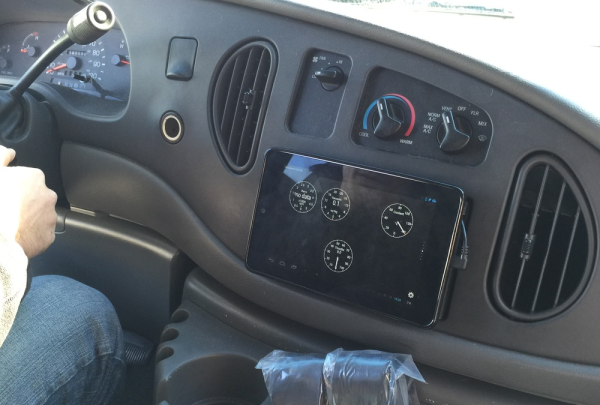
Many new vehicles come with computers built into the dashboard. They can be very handy with features like GPS navigation, Bluetooth connectivity, and more. Installing a computer into an older car can sometimes be an expensive process, but [Florian] found a way to do it somewhat inexpensively using a Nexus 7 tablet.
The size of the Nexus 7 is roughly the same as a standard vehicle double-din stereo slot. It’s not perfect, but pretty close. [Florian] began by building a proof of concept mounting bracket. This model was built from sections of MDF hot glued and taped together. Plastic double-din mounting brackets were attached the sides of this new rig, allowing it to be installed into the dashboard.
Once [Florian] knew that the mounting bracket was feasible, it was time to think about power. Most in-vehicle devices are powered from the cigarette lighter adapter. [Florian] went a different direction with this build. He started with a cigarette lighter to USB power adapter, but he cut off the actual cigarette lighter plug. He ended up wiring this directly into the 12V line from the stereo’s wiring harness. This meant that the power cord could stay neatly tucked away inside of the dashboard and also leave the cigarette lighter unused.
[Florian] then wanted to replace the MDF frame with something stronger and nicer. He modeled up his idea in Solidworks to make sure the measurements would be perfect. Then the pieces were all laser cut at his local Techshop. Once assembled, the plastic mounting brackets were placed on the sides and the whole unit fit perfectly inside of the double-din slot.
When it comes to features, this van now has it all. The USB hub allows for multiple USB devices to be plugged in, meaning that Nexus only has a single wire for both power and all of the peripherals. Among these peripherals are a USB audio interface, an SD card reader, and a backup camera. There is also a Bluetooth enabled OBD2 reader that can monitor and track the car’s vitals. If this project seems familiar to you, it’s probably because we’ve seen a remarkably similar project in the past.


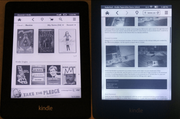
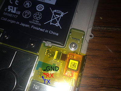 The first step was to crack open the case and locate the serial port. [WarriorRocker] soldered a small three pin header to the pads to make it easier to work on his device as needed. He then connected the Kindle to his PC using a small serial to USB adapter. Pulling up the command prompt was as simple as running Putty and connecting to the correct COM port. If the wires are hooked up correctly, then it just takes a press of the enter key to pull up the login prompt.