Mick Jagger famously said that you cain’t always get what you want. But this is Hackaday, and we make what we want or can’t get. Case in point: [Andrew Tudoroi] is drawn to retro LEDs and wanted one of Pimoroni’s micro-LED boards pretty badly, but couldn’t get his hands on one. You know how this ends — with [Andrew] designing his first PCB.
The Pitanga hat is equally inspired by additional fruit that [Andrew] had lying around in the form of an 8devices Rambutan board. (Trust us, it’s a fruit.) With some research, he discovered the HT16K33 LED driver, which checked all the boxen.
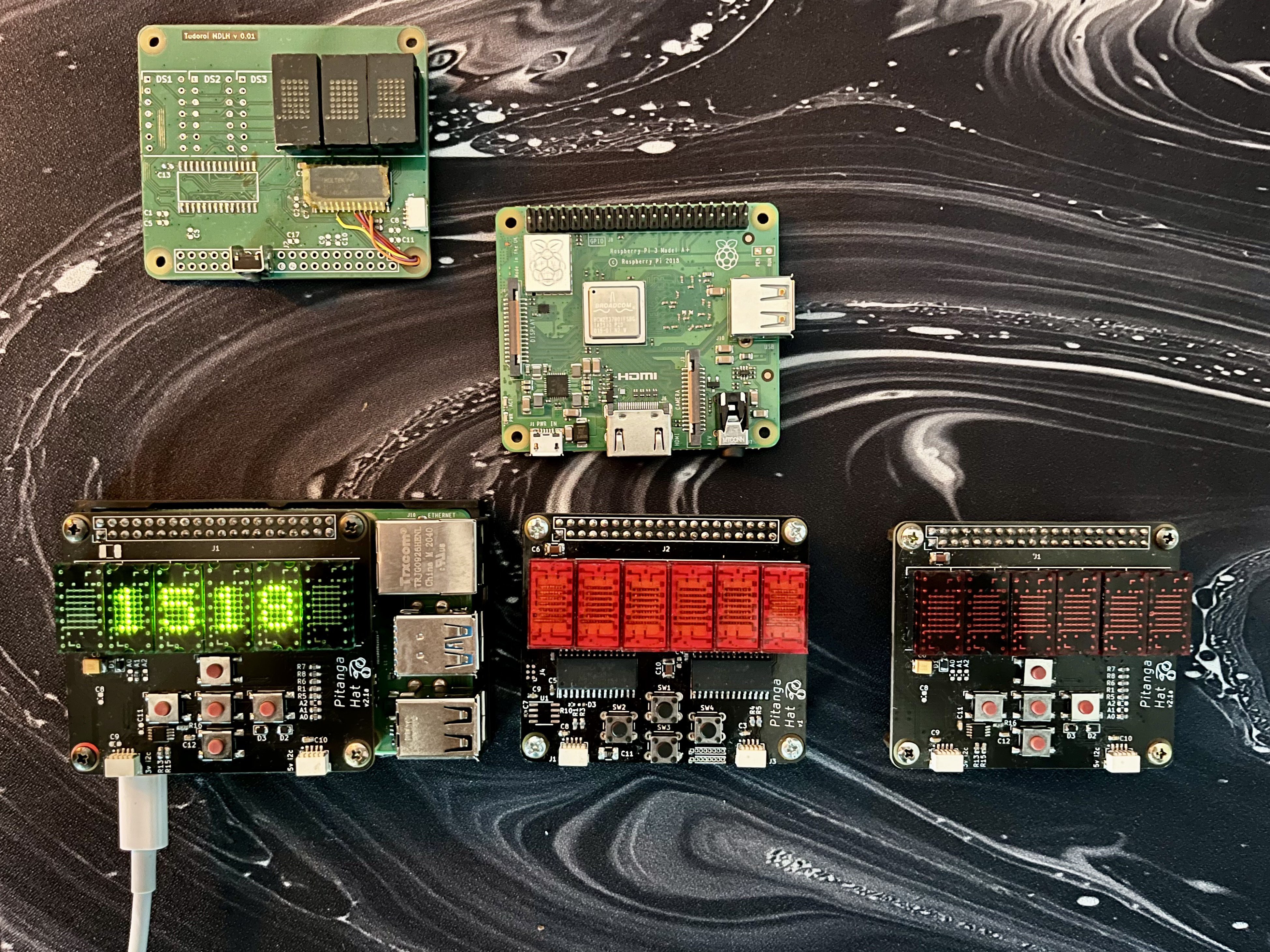 The first version worked, but needed what looks like a couple of bodge wires. No shame in that! For the next revision, [Andrew] added buttons and decided to make it into a Raspberry Pi HAT.
This HAT is essentially a simple display with a basic input device, and a beauty at that. You can see all the various cool displays that [Andrew] tried both here and in the project log. Although he included pads for an ARM M0 microcontroller, he never did populate it. Maybe in the future.
Of course, this project was not without its challenges. For one thing, there was power compatibility to wrestle with. The Pi can sometimes work with I²C devices at 5 V, but this isn’t ideal long-term. So [Andrew] put the LED driver on the 3.3 V I²C bus. Despite the data sheet calling for 4.5 to 5.5 V, the setup worked fine. But for better reliability, [Andrew] threw a dedicated I²C logic level converter chip into the mix.
Don’t forget, you can run a noble amassment of HATs with the PiSquare.