This excellent content from the Hackaday writing crew highlights recurring topics and popular series like Linux-Fu, 3D-Printering, Hackaday Links, This Week in Security, Inputs of Interest, Profiles in Science, Retrotechtacular, Ask Hackaday, Teardowns, Reviews, and many more.
It’s a common sight in the farming areas of the world — a group of enterprising automotive hackers take a humble economy car, and saw the roof off, building a convertible the cheapest way possible. Being the city dwelling type, I always looked on at these paddock bashing antics with awe, wishing that I too could engage in such automotive buffoonery. This year, my time would come — I was granted a hatchback for the princely sum of $100, and the private property on which to thrash it.
However, I wasn’t simply keen to recreate what had come before. I wanted to take this opportunity to build a solution for those who had suffered like me, growing up in the confines of suburbia. Surrounded by houses and with police on patrol, it simply isn’t possible to cut the roof off a car and drive it down to the beach without getting yourself in altogether too much trouble. But then again, maybe there’s a way.
The goal was to build the car in such a way that its roof could be cut off, but remain attached by removable brackets. This would allow the car to be driven around with the roof still attached, without raising too much suspicion from passing glances. For reasons of legality and safety, our build and test would be conducted entirely on private property, but it was about seeing what could be done that mattered.
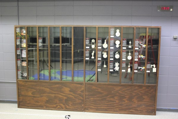
Museum exhibits are difficult to make, and they’re always breaking down; especially the interactive ones. This is a combination of budget, building a one-off, and the incredibly harsh abuse they take from children.
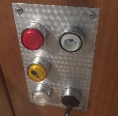
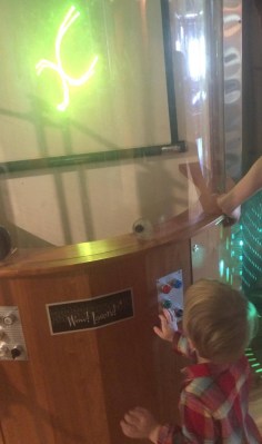
My first exhibit is an interactive laser show that turns waveforms from music into laser patterns, and different types of music have very different patterns. I knew from talking to the museum staff that industrial buttons were a necessity, but it turns out that industrial buttons are made under the assumption that tiny creatures won’t be constantly mashing, twisting, and (ew ew ew) licking the buttons. After a while, the buttons (and poor knob) were trashed.
The button face has been removed, and the knob is spinning freely.
Buttons at toddler level are in a vulnerable position.
The second exhibit is also interactive, but in this case it’s just a simple button that turns on a thing for a while, then shuts it off. You can read more about the Periodic Table of Motion on the project page. Here I thought; let’s use capacitive touch, put the sensor behind two layers of acrylic for protection, and then there won’t be any moving parts to break. I built a bunch of units, tested it for weeks, then installed it. Instant failure despite my diligence.
Something is different about the installation from my test environment. It might be the second layer of acrylic contributing. Maybe it’s the power supply and a strange ground issue. Maybe the room’s fluorescent lights are creating an electromagnetic field that is interrupting the sensor, or the carpet is causing static buildup that is somehow causing the midichlorians to reverse polarity and discharge through the base plate of prefabulated aluminite. In some of the cells, the button doesn’t work. In other cells it is extremely sensitive. In one column of the table (columns share a common piece of acrylic among 5 cells), a single touch will trigger all 5.
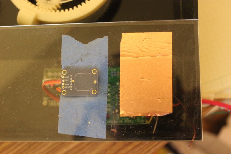
The circuit is an ATtiny with a 2.2M resistor between two pins, one of which connects via a short wire to a soldered connection to a piece of copper tape on the underside of an acrylic piece. The ATtiny is using the capsense library, which has features for automatic recalibration. Because of the way it is installed, I can’t reprogram them to adjust their sensitivity while inside the enclosure, so tweaking them post-install is not an option. I thought I could isolate the problem and use an existing capacitive touch sensor breakout of the AT42QT1010 hooked up to just power, but it had the exact same issue, meaning it’s either the power supply, the enclosure, or the room.
Side-by-side tests of copper tape+Arduino and AT42QT1010 had similar problems.
There are three paths I can go down now:
Find the problem and solve it
Switch to a photoresistor
Petition Hackaday for a better solution
Finding the problem and solving it will be a long and difficult path, especially since the museum environment is somehow and inexplicably different from the test environment. The photoresistor option has promise; when the user puts their hand over the paper button the light level changes. Some early testing indicates that it is easy to detect instantaneous change, and a trailing average and adjusting threshold make it robust enough for changing lighting conditions throughout the day. Further, it’s a simple change to the code, and the existing circuit board will accommodate the adjustment.
As for the third option…
What have you done for child-compatible touch interfaces that are robust enough to handle uncertain environments and harsh abuse? What buttons, knobs, and other interactive elements have you used?
Hackaday is all about the neat hacks and the repurposing of old components into new projects, but many people then try to take those projects and turn them into businesses. We’ve seen lots of people offer their stuff as kits and sell them on Tindie, with the rare few going on to develop a consumer electronic product at scale.
The Hackaday Prize 2017 Best Product highlights this journey. “Scale” itself is a vague term, but essentially it means to be able to produce enough to meet market demand. We hope that market demand is roughly 7 billion units, purchasing yearly, but the reality is that it is somewhere between 1 and a few hundred thousand, with very big differences in manufacturing at each order of magnitude. So how do you start with a proof of concept and design your product from the very beginning to be optimized to scale to meet whatever demand you can handle?
For one reason or another, Hackaday has an extended family of ridiculously capable contributors. One of the most illustrious is [Bil Herd], Commodore refugee, electronic engineer, medic, and all-around awesome guy. He’ll be joining us over on Hackaday.io this Friday for a Hack Chat on Electronics Design.
This Friday, we’re hosting a Hack Chat with [Bil]. If you want to talk Commodore, this is the guy. If you want to talk about PLAs and programmable digital logic, this is the guy. If you want to know how to build a system from scratch in just a few months, [Bil]’s your man. [Bil] has decades of experience and his design work was produced by the millions. You’ll rarely come across someone with as much experience, and he’ll be in our Hack Chat this Friday.
[Bil] has a long career in electronics design, beginning with fixing CB radios and televisions back when fixing TVs was still a thing. Eventually, he worked his way up the engineering ladder at Commodore Business Machines where he designed the Commodore TED machines and the amazing Commodore 128.
After surviving Commodore, [Bil] has worked at a trauma center in Camden, NJ, flown with medics in the Army, and eventually came over to Hackaday where he produces videos from subjects ranging from direct digital synthesis, programmable logic, active filters, and how CMOS actually works. Basically, if it involves electronics, [Bil] knows what’s up.
Oh, as an added bonus, we get to name a puppy this week. [Bil] got a new puppy and it needs a name. Send in your suggestions!
Here’s How To Take Part:
Our Hack Chats are live community events on the Hackaday.io Hack Chat group messaging. This hack chat will take place at noon Pacific time on Friday, June 16th. Confused about where and when ‘noon’ is? Here’s a time and date converter!
Log into Hackaday.io, visit that page, and look for the ‘Join this Project’ Button. Once you’re part of the project, the button will change to ‘Team Messaging’, which takes you directly to the Hack Chat.
You don’t have to wait until Friday; join whenever you want and you can see what the community is talking about
There are two main applications for managing 3D prints and G-Code generation. Cura is a fantastic application that is seeing a lot of development from the heavy hitters in the industry. Initially developed by Ultimaker, Lulzbot has their own edition of Cura, It’s the default software packaged with thousands of different printers. Slic3r, as well, has seen a lot of development over the years and some interesting hacks. Do you want to print non-planar surfaces? Slic3r can do that. Slic3r and Cura are two sides of the CAM part of the 3D printing coin, although Cura is decidedly the prettier side.
The ability to combine the extensibility of Slic3r with the user interface of Cura has been on our wish list for a while now. It’s finally time. [Josef Prusa] has released PrusaControl, a 3D printing CAM solution that combines the best of Slic3r into a fantastic, great looking package. What are the benefits? What’s it like? Check that out below.
PCB art is getting better and better every year. This year, though, is knocking it out of the park. In March, [Andrew Sowa] turned me into money. More recently, [Trammell Hudson] has explored the layers of OSH Park soldermask and silk to create a masterpiece. Now, we’re moving up to full-blown art. [Blake Ramsdell] worked with OSH Park to create a full panel of art in gold, fiberglass, soldermask, and silkscreen. It’s 22×16 inches, and it’s fantastic.
There’s an independent Hackaday meetup going down in Hong Kong this week. The subject of the meetup will be vacuum systems for electron beam melting, mass spectrometry, and building Nixie tubes.
Why does my circuit still work when I remove some caps? This question was posed to the EEVBlog forums, with a picture attached of the worst mess of wires I’ve ever seen. This is — supposedly — not a joke, and a complete, functional CPU built out of 74HC series logic on thirty or so solderless breadboards. A weird bonus of access to the tip line at Hackaday means everyone here becomes experts in the field of absurdly constructed electronics. Want to see the worst PCB ever? We’ve seen it. This is, without question, the most rats nest electronic project anyone has ever built.
[Adam West] died this weekend at the age of 88. [West] is perhaps best known for his performance in Lookwell as a crime-solving, washed-up TV action hero. He is survived by his wife, Marcelle, and six children.
We often read about the minicomputers of the 1960s, and see examples of their use in university research laboratories or medium-sized companies where they might have managed the accounts. It’s tempting though to believe that much of the world in those last decades of the analogue era remained untouched by computing, only succumbing in the decade of the microcomputer, or of the widespread use of the Internet.
What could be more synonymous with the pre-computing age than the mail system? Hundreds of years of processing hand-written letters, sorted by hand, transported by horses, boats, railroads and then motor transport, then delivered to your mailbox by your friendly local postman. How did minicomputer technology find its way into that environment?
Thus we come to today’s film, a 1970 US Postal Service short entitled “Reading And Sorting Mail Automatically”. In it we see the latest high-speed OCR systems processing thousands of letters an hour and sorting them by destination, and are treated to a description of the scanning technology.
If a Hackaday reader in 2017 was tasked with scanning and OCR-ing addresses, they would have high-resolution cameras and formidable computing power at their disposal. It wouldn’t be a trivial task to get it right, but it would be one that given suitable open-source OCR software could be achieved by most of us. By contrast the Philco engineers who manufactured the Postal Service’s scanners would have had to create them from scratch.
This they performed in a curiously analogue manner, with a raster scan generated by a CRT. First a coarse scan to identify the address and its individual lines, then a fine scan to pick out the line they needed. An optical sensor could then pick up the reflected light and feed the information back to the computer for processing.
The description of the OCR process is a seemingly straightforward one of recognizing the individual components of letters which probably required some impressive coding to achieve in the limited resources of a 1960s minicomputer. The system couldn’t process handwriting, instead it was reserved for OCR-compatible business mail.
Finally, the address lines are compared with a database of known US cities and states, and each letter is routed to the appropriate hopper. We are shown a magnetic drum data store, the precursor of our modern hard drives, and told that it holds an impressive 10 megabytes of data. For 1970, that was evidently a lot.
It’s quaint to see what seems to be such basic computing technology presented as the last word in sophistication, but the truth is that to achieve this level of functionality and performance with the technology of that era was an extremely impressive achievement. Sit back and enjoy the film, we’ve placed it below the break.








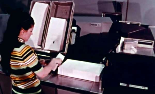
 This they performed in a curiously analogue manner, with a raster scan generated by a CRT. First a coarse scan to identify the address and its individual lines, then a fine scan to pick out the line they needed. An optical sensor could then pick up the reflected light and feed the information back to the computer for processing.