Laser Welding Helps YouTuber Get Ahead With Aluminum Sheet

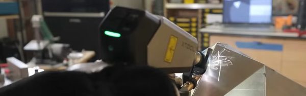
Laser Welding is apparently the new hotness, in part because these sci-fi rayguns masquerading as tools are really cool. They cut! They weld! They Julienne Fry! Well, maybe not that last one. In any case, perhaps feeling the need to cancel out that coolness as quickly as he possibly could, YouTuber [Wesley Treat] decided to make a giant version of his own head.

[Wesely] had previously been 3D scanned as part of the maker scans project, which you can find over on Printables. Those of you who really hate YouTubers, take note: finally you have something  to take your frustrations out on. [Wesely] takes that model into Blender to decimate and decapitate– fans of the band Tyr may wonder if the model questioned his sword–before feeding that head through an online papercraft tool called PaperMaker to generate cut files for his CNC. There are also a lot of welding montages interspersed there as he practices with the new tool. [Wesely] did first try out his new raygun on steel in a previous video, but even knowing that, he makes the learning curve on these lasers look quite scalable.

While we’re not likely to follow in [Wesely]’s footsteps and create our own low-poly Zardoz– Zardozes? Zardii?– using a papercraft toolchain and CNC equipment with sheet aluminum is absolutely a great idea worth stealing. It’s very similar to what another hacker did with PCBs— though that project was perhaps more reasonable in scale and ego.

We are no strangers to papercrafts that use actual paper here, either, having featured everything from model retrocomputers to fully-mobile strandbeasts. 

Continue reading “Laser Welding Helps YouTuber Get Ahead With Aluminum Sheet”

There Are No LEDs Around The Face Of This Clock

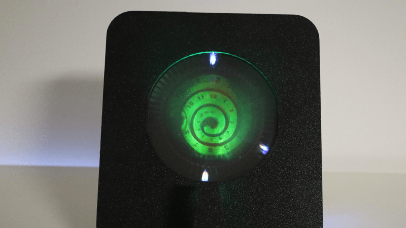
This unusual clock by [Moritz v. Sivers] looks like a holographic dial surrounded by an LED ring, but that turns out to not be the case. What appears to be a ring of LEDs is in fact a second hologram. There are LEDs but they are tucked out of the way, and not directly visible. The result is a very unusual clock that really isn’t what it appears to be.

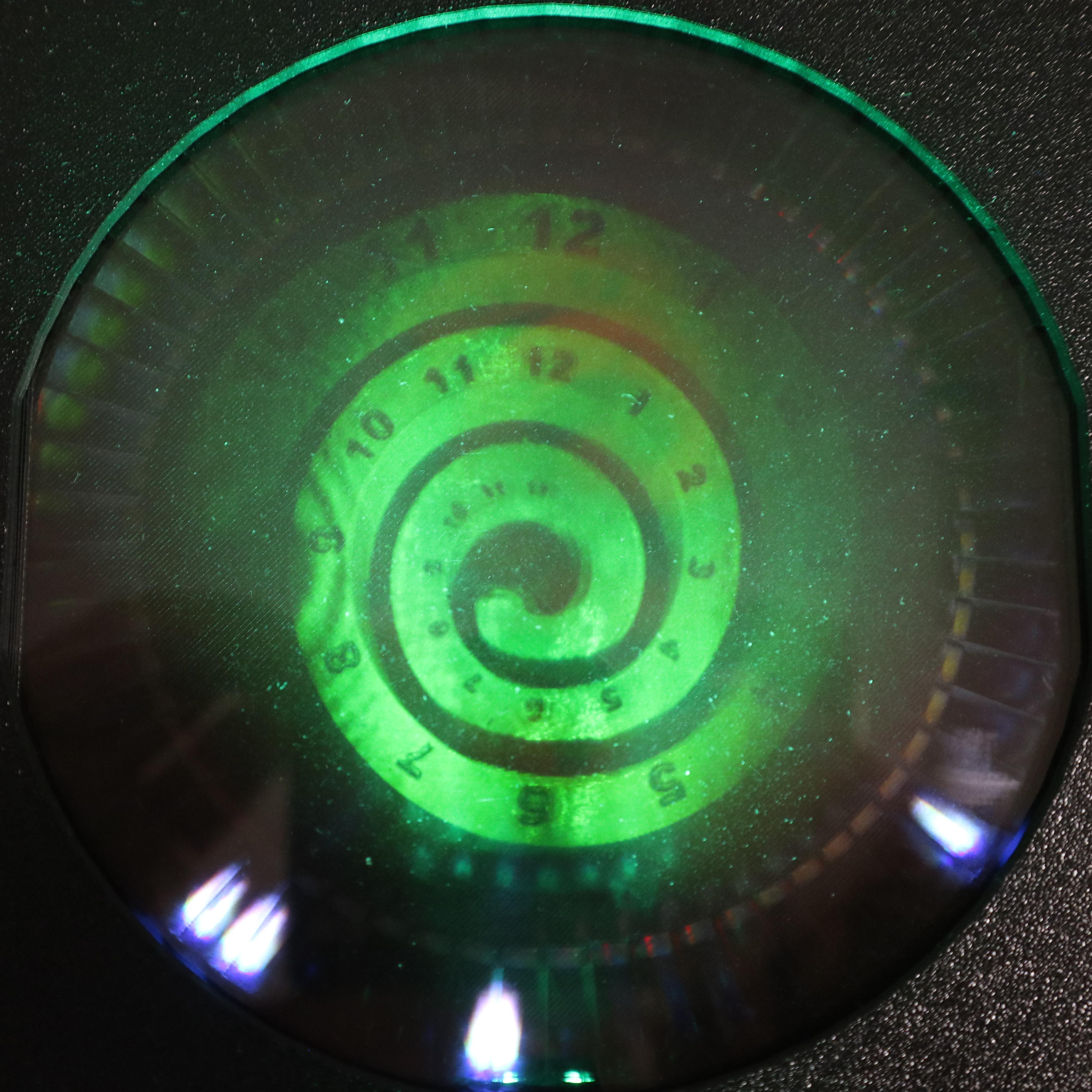
The face of the clock is a reflection hologram of a numbered spiral that serves as a dial. A single LED – the only one visibly mounted – illuminates this hologram from the front in order to produce the sort of holographic image most of us are familiar with, creating a sense of depth.

The lights around the circumference are another matter. What looks like a ring of LEDs serving as clock hands is actually a transmission hologram made of sixty separate exposures. By illuminating this hologram at just the right angle with LEDs (which are mounted behind the visible area), it is possible to selectively address each of those sixty exposures. The result is something that really looks like there are lit LEDs where there are in fact none.

[Moritz] actually made two clocks in this fashion. The larger green one shown here, and a smaller red version which makes some of the operating principles a bit more obvious on account of its simpler construction.

If it all sounds a bit wild or you would like to see it in action, check out the video (embedded below) which not only showcases the entire operation and assembly but also demonstrates the depth of planning and careful execution that goes into multi-exposure of a holographic plate.

[Moritz v. Sivers] is no stranger to making unusual clocks. In fact, this analog holographic clock is a direct successor to his holographic 7-segment display clock. And don’t miss the caustic clock, nor his lenticular clock.

Continue reading “There Are No LEDs Around The Face Of This Clock”

Color Mixing Spray Paint On The Fly

One of the problems with being a graffiti artist is that you have to carry around a different spray can for each color you intend to use. [Sandesh Manik] decided to solve this problem by building a rig that can produce a wider range of colors by mixing the paint from several cans at once.

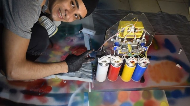
The project is called Spectrum. It uses four off-the-shelf spray paint cans—colored red, blue, yellow, and white—and mixes them to create a wider range of colors. All four cans are hooked up to a single output nozzle via a nest of tubing and a four-to-one tube manifold. Key to controlling the flow of paint is a custom device which [Sandesh] calls the “rotary pinch valve,” with one fitted to the feed line coming from each spray can. These valves use a motor-driven lever to pinch a plastic tube shut, allowing them to control the paint flow. This design keeps the mechanism and paint completely separate, which was important to stop paint from fouling the valves in short order. It also prevents backflow, which keeps the paint going towards the outlet and prevents ugly messes. By quickly actuating the valve, the paint flow from each can is modulated to mix various colors as desired.

The mixing valves are under the command of an Arduino Nano. The microcontroller reads a series of knobs to select the amount of each component color to mix, and displays relevant information on a screen. Then, when a push button is pressed, the valves are actuated to spit out the right amount of each paint from the atomizer nozzle. [Sandesh] went so far as to include an advanced “gradient” mode, where a force-sensitive button allows the device to transition smoothly from one color to another depending on how hard the button is pushed.

It’s a neat concept which we’d love to see explored further, perhaps with a more traditional selection of CMYK paints rather than the more unusual red, yellow, blue, and white. We’ve also seen some fun spray paint projects before, like this neat wall-mount plotter.

Continue reading “Color Mixing Spray Paint On The Fly”

Love Complex Automata? Don’t Miss The Archer

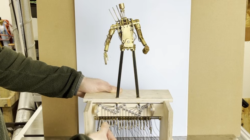
[Oliver Pett] loves creating automata; pieces of art whose physicality and motion come together to deliver something unique. [Oliver] also has a mission, and that mission is to complete the most complex automata he has ever attempted: The Archer. This automaton is a fully articulated figure designed to draw arrows from a quiver, nock them in a bow, draw back, and fire — all with recognizable technique and believable motions. Shoot for the moon, we say!

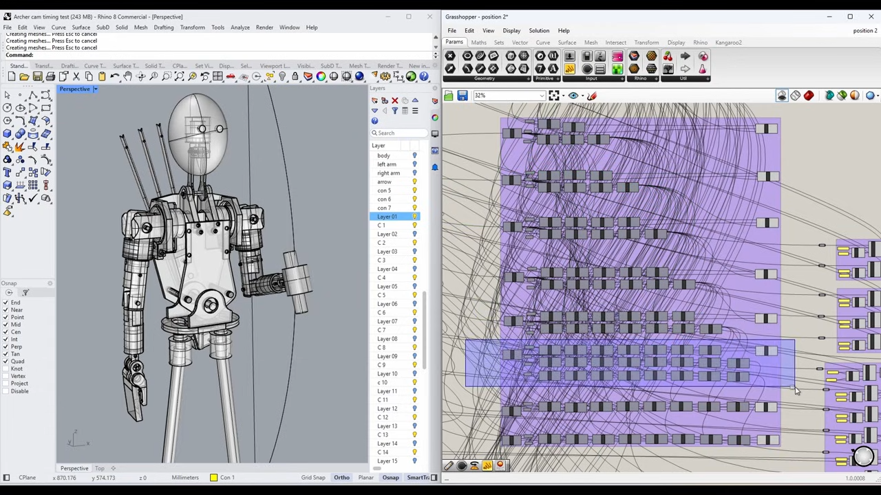
He’s documenting the process of creating The Archer in a series of videos, the latest of which dives deep into just how intricate and complex of a challenge it truly is as he designs the intricate cams required.

A digital, kinematic twin in Rhino 3D helps [Oliver] to choose key points and determine the cam profiles required to effect them smoothly.
In simple automata rotational movement can be converted by linkages to create the required motions. But for more complicated automata (like the pen-wielding Maillardet Automaton), cams provide a way to turn rotational movement into something much more nuanced. While creating the automaton and designing appropriate joints and actuators is one thing, designing the cams — never mind coordinating them with one another — is quite another. It’s a task that rapidly cascades in complexity, especially in something as intricate as this.

[Oliver] turned to modern CAD software and after making a digital twin of The Archer he’s been using it to mathematically generate the cam paths required to create the desired movements and transitions, instead of relying on trial and error. This also lets him identify potential collisions or other errors before any metal is cut. The cams are aluminum, so the fewer false starts and dead ends, the better!

Not only is The Archer itself a beautiful piece of work-in-progress, seeing an automaton’s movements planned out in this way is a pretty interesting way to tackle the problem. We can’t wait to see the final result.

Thanks [Stephen] for the tip!

Inside A Dutch Street Organ: The Art Of Mechanical Music-Making

[James]’ Mechanical Organ of Dutch origin has been around longer than he has, but thanks to being rebuilt over the years and lovingly cared for, it delivers its unique performances just as well as it did back in the day. Even better, we’re treated to a good look at how it works.

The organ produces music by playing notes on embedded instruments, which are themselves operated by air pressure, with note arrangements read off what amounts to a very long punch card. [James] gives a great tour of this fantastic machine, so check it out in the video embedded below along with a couple of its performances.

Continue reading “Inside A Dutch Street Organ: The Art Of Mechanical Music-Making”

DIY Wall-Plotter Does Generative Art, But Not As We Know It

[Teddy Warner]’s GPenT (Generative Pen-trained Transformer) project is a wall-mounted polargraph that makes plotter art, but there’s a whole lot more going on than one might think. This project was partly born from [Teddy]’s ideas about how to use aspects of machine learning in ways that were really never intended. What resulted is a wall-mounted pen plotter that offers a load of different ‘generators’ — ways to create line art — that range from procedural patterns, to image uploads, to the titular machine learning shenanigans.

There are loads of different ways to represent images with lines, and this project helps explore them.

Want to see the capabilities for yourself? There’s a publicly accessible version of the plotter interface that lets one play with the different generators. The public instance is not connected to a physical plotter, but one can still generate and preview plots, and download the resulting SVG file or G-code.

Most of the generators do not involve machine learning, but the unusual generative angle is well-represented by two of them: dcode and GPenT.

dcode is a diffusion model that, instead of converting a text prompt into an image, has been trained to convert text directly into G-code. It’s very much a square peg in a round hole. Visually it’s perhaps not the most exciting, but as a concept it’s fascinating.

The titular GPenT works like this: give it a scrap of text inspiration (a seed, if you will), and that becomes a combination of other generators and parameters, machine-selected and stacked with one another to produce a final composition. The results are unique, to say the least.

Once the generators make something, the framed and wall-mounted plotter turns it into physical lines on paper. Watch the system’s first plot happen in the video, embedded below under the page break.

This is a monster of a project representing a custom CNC pen plotter, a frame to hold it, and the whole software pipeline both for the CNC machine as well as generating what it plots. Of course, the journey involved a few false starts and dead ends, but they’re all pretty interesting. The plotter’s GitHub repository combined with [Teddy]’s write up has all the details one may need.

It’s also one of those years-in-the-making projects that ultimately got finished and, we think, doing so led to a bit of a sigh of relief on [Teddy]’s part. Most of us have unfinished projects, and if you have one that’s being a bit of a drag, we’d like to remind you that you don’t necessarily have to finish-finish a project to get it off your plate. We have some solid advice on how to (productively) let go.

Continue reading “DIY Wall-Plotter Does Generative Art, But Not As We Know It”

A cuboctahedron (a kind of polyhedron) made out of LED filaments is being held above a man's hand in front a computer screen.

The Graph Theory Of Circuit Sculptures

Like many of us, [Tim]’s seen online videos of circuit sculptures containing illuminated LED filaments. Unlike most of us, however, he went a step further by using graph theory to design glowing structures made entirely of filaments.

The problem isn’t as straightforward as it might first appear: all the segments need to be illuminated, there should be as few powered junctions as possible, and to allow a single power supply voltage, all paths between powered junctions should have the same length. Ideally, all filaments would carry the same amount of current, but even if they don’t, the difference in brightness isn’t always noticeable. [Tim] found three ways to power these structures: direct current between fixed points, current supplied between alternating points so as to take different paths through the structure, and alternating current supplied between two fixed points (essentially, a glowing full-bridge rectifier).

To find workable structures, [Tim] represented circuits as directed graphs, with each junction being a vertex and each filament a directed edge, then developed filter criteria to find graphs corresponding to working circuits. In the case of power supplied from fixed points, the problem turned out to be equivalent to the edge-geodesic cover problem. Graphs that solve this problem are bipartite, which provided an effective filter criterion. The solutions this method found often had uneven brightness, so he also screened for circuits that could be decomposed into a set of paths that visit each edge exactly once – ensuring that each filament would receive the same current. He also found a set of conditions to identify circuits using rectifier-type alternating current driving, which you can see on the webpage he created to visualize the different possible structures.

We’ve seen some artistic illuminated circuit art before, some using LED filaments. This project doesn’t take exactly the same approach, but if you’re interested in more about graph theory and route planning, check out this article.