Internals of the Blu-ray player, showing both the blu-ray drive and the custom PCBs

An Ingenious Blu-Ray Mini-Disk Player

[befi] brings us a project as impressive as it is reminiscent of older times, a Blu-Ray mini disk player. Easily fitting inside a pocket like a 8 cm CD player would, this is a labour of love and, thanks to [befi]’s skills both in electronics and in using a dremel tool.

A BluRay drive was taken apart, for a start, and a lot of case parts were cut off; somehow, [befi] made it fit within an exceptionally tiny footprint, getting new structural parts printed instead, to a new size. The space savings let him put a fully custom F1C100S-powered board with a number of unique features, from a USB-SATA chip to talk to the BluRay drive, to USB pathway control for making sure the player can do USB gadget mode when desired.

There’s an OLED screen on the side, buttons for controlling the playback, power and battery management – this player is built to a high standard, ready for day-to-day use as your companion, in the world where leaving your smartphone as uninvolved in your life as possible is a surprisingly wise decision. As a fun aside, did you know that while 8 cm CDs and DVDs existed, 8 cm BluRay drives never made it to market? If you’re wondering how is it that [befi] has disks to play in this device, yes, he’s used a dremel here too.

Everything is open-sourced – 3D print files, the F1C100S board, and the Buildroot distribution complete with all the custom software used. If you want to build such a player, and we wouldn’t be surprised if you were, there’s more than enough resources for you to go off. And, if you’re thinking of building something else in a similar way, the Buildroot image will be hugely helpful.

Want some entertainment instead? Watch the video embedded below, the build journey is full of things you never knew you wanted to learn. This player is definitely a shining star on the dark path that is Blu-Ray, given that our most popular articles on Blu-Ray are about its problems.

Continue reading “An Ingenious Blu-Ray Mini-Disk Player”

Reverse Engineering The Behringer Ultranet Protocol

Ultranet is a protocol created by audio manufacturer Behringer to transmit up to 16 channels of 24-bit sound over a Cat-5 cable. It’s not an open standard, though: Behringer doesn’t offer an API or protocol description to build your own Ultranet devices. But that didn’t stop [Christian Nödig], thanks to a defective mixer, he poked into the signals and built his own Ultranet receiver.

Ultranet runs over Cat-5 ethernet cables but isn’t an ethernet-based protocol. The electrical protocols of Ultranet are identical to Ethernet, but the signaling is different, making it a Level 1 protocol. So, you can use any Cat-5 cable for Ultranet, but you can’t just plug an Ultranet device into an Ethernet one. Or rather, you can (and neither device should explode), but you won’t get anything out of it.

Instead, [Christian]’s exploration revealed that Ultranet is based on another standard: AES/EBU, the bigger professional brother of the SPD/IF socket on HiFi systems. This was designed to carry digital audio over an XLR cable, and Behringer has taken AES/EBU and tweaked it to run over a single twisted pair. With two twisted pairs in the cable carrying a 192 kbps signal, you get sixteen channels of 24-bit audio in total over two twisted pairs inside the Cat-5 cable.

That’s a bit fast for a microcontroller to decode reliably, so [Christian] uses the FPGA in an Arduino Vidor 4000 MKR in his receiver with an open-source AES decoder core to receive and decode the Ultranet signal into individual channels, which are passed to an ADC and analog output.

In effect, [Christian] has built a 16-channel mixer, although the mixing aspect is too primitive for actual use. It would be great for monitoring, though, and it’s a beautiful description of how to dig into protocols like Ultranet that look locked up but are based on other, more open standards.

Continue reading “Reverse Engineering The Behringer Ultranet Protocol”

Sonolithography With The Raspberry Pi Pico

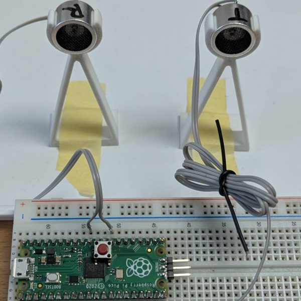
You can do some wild things with sound waves, such as annoy your neighbours or convince other road users to move out of your way. Or, if you get into sonolithography like [Oliver Child] has, you can make some wild patterns with ultrasound.

Sonolithography is a method of patterning materials on to a surface using finely-controlled sound waves. To achieve this, [Oliver] created a circular array of sixteen ultrasonic transducers controlled via shift registers and gate driver ICs, under the command of a Raspberry Pi Pico. He then created an app for controlling the transducer array via an attached computer with a GUI interface. It allows the phase and amplitude of each element of the array to be controlled to create different patterns.

Creating a pattern is then a simple matter of placing the array on a surface, firing it up in a given drive mode, and then atomising some kind of dye or other material to visualize the pattern of the acoustic waves.

It could be a useful tool for studying the interactions of ultrasonic waves, or it could just be a way to make neat patterns in ink and dye if that’s what you’re into. [Oliver] notes the techniques of sonolithography could also have implications in biology or fabrication in future, as well. If you found this interesting, you might like to study up on ultrasonic levitation, too!

Up Close And Personal With A MEMS Microphone

If you’ve ever wondered what lies beneath the barely visible hole in the can of a MEMS microphone, you’re in luck, because [Zach Tong] has a $10 pair of earbuds to sacrifice for the cause and an electron microscope.

For the uninitiated, MEMS stands for microelectromechanical systems, the tiny silicon machines that power some of the more miraculous functions of smartphones and other modern electronics. The most familiar MEMS device might be the accelerometer that gives your phone a sense of where it is in space; [Zach] has a deep dive into MEMS accelerometers that we covered a while back.

MEMS microphones seem a little bit easier to understand mechanically, since all they have to do is change vibrations in air into an electrical signal. The microphone that [Zach] tore down for this video is ridiculously small; the SMD device is only about 3 mm long, with the MEMS chip under the can a fraction of a millimeter on a side. After some overall views with the optical microscope, [Zach] opened the can and put the guts under his scanning electron microscope. The SEM shots are pretty amazing, revealing a dimpled silicon diaphragm over a second layer with holes etched right through it. The dimples on the diaphragm nest into the holes, forming an air-dielectric capacitor whose capacitance varies as sound waves vibrate the diaphragm.

The most visually interesting feature, though, might be the deep cavity lying behind the two upper surfaces. The cavity, which [Zach] says bears evidence of having been etched by the deep reactive ion etching method, has cool-looking corrugations in its walls. The enormity of the cavity relative to the thin layers covering it suggests it’s a resonating cavity for the sound waves.

Thanks to [Zach] for this in-depth look at a device that’s amazingly complex yet remarkably simple.

Continue reading “Up Close And Personal With A MEMS Microphone”

CT Scanner Reveals The Difference Between Real And Fake AirPods

These days, you have to be careful what you buy. Counterfeit hardware is everywhere, especially when you’re purchasing things sight unseen over the Internet. [Jon Bruner] recently set out to look at a bunch of fake AirPod clones, and found that the similarities between the imposters and the real thing are only skin deep. A CT scan reveals all.

As you might expect, Apple’s AirPods are a fine example of miniaturization. They’re packed to the gills with hardware, with very little wasted space inside. Flexible PCBs hook up the electronics in an elegant and tidy fashion. Three tiny MEMS microphones are on board to capture the user’s voice and filter out noise. The battery that runs the show is a hefty lithium-ion coin cell which fills almost all the empty space behind the audio driver.

By contrast, the fakes look positively weedy inside. They cut out the bonus microphones, using just one to do the job. Wires link up the different components, with unimpressive blobby soldering visible that has splattered around the internal enclosure. Even the cases are lower-tech, with a weaker battery and a poorer charging solution. Hilariously, cheaping out on the tech makes the fakes lighter, so they compensate by adding weights to create a sense of heft for the user.

It’s amazing how much is revealed by a CT scan, that doesn’t even require opening the devices to tear them down. Fake hardware really is a scourge that many in the tech industry find themselves fighting against on a regular basis.

Noise Cancelling Isn’t As Easy As You’d Think

On the face of it, producing a set of noise cancelling headphones should be a relatively straightforward project. But as [Pete Lewis] found out, things are not always as they seem. The result is a deep dive into microphone specifications, through which most of us could probably learn something.

Noise cancelling headphones have a set of microphones which provide anti-phase noise through an amplifier to the ‘phones, thus in theory cancelling out the external noise. Since [Pete] is a musician this pair would have to be capable of operating at high noise levels, so he checked the spec for his microphone and with an acoustic overload point at 124 dB for a 115 environment he was ready to go.

Unfortunately these ‘phones showed distortion, which brings us back to the acoustic overload point. This is the sound level at which the microphone has 10% distortion, which is a very high figure, and certainly meant there was enough distortion to be audible at the lower level. After a search for a higher spec microphone and a move to a digital codec-based solution with an ESP32 he eventually cracks it though, leading to an inexpensive set of noise cancelling headphones for high-noise environments.

If distortion interests you, it’s a subject we’ve visited in the past.

Header image: fir0002, GFDL 1.2.

XMems Cowell MEMS-based tweeter on top of dynamic driver. (Credit: xMEMS)

After MEMS Microphones, MEMS Speakers Enter The Market

These days it’s hard to not come across solid-state (micro-electromechanical systems, MEMS) microphones, as they are now displacing electret microphones almost everywhere due to their small size and low cost. Although MEMS speakers are not impossible, creating a miniature speaker that can both displace a lot of air (‘volume’) and accurately reproduce a wide range of frequencies – unlike simple piezo buzzers – is a lot tougher. Here a startup called xMEMS figures that they have at least partially cracked the code with their piezoMEMS speakers, with Creative using the Cowell version in their brand-new Aurvana Ace in-ear monitors. Continue reading “After MEMS Microphones, MEMS Speakers Enter The Market”