Mini Drill Made From A Motor

We love this hacked-together mini drill by [BuenaTec] that uses a DC7.2V 10K-RPM motor with a 1/8” Dremel chuck added on. Power is supplied by a USB-A cable with the data wires cut off, with a switch controlling the voltage and a rectifier diode protecting the USB port or battery pack from back voltage from the motor.

The drill isn’t very powerful, only able to bore holes in PCBs, plastic, and similar soft materials. However, you could see how just a couple more components could make it even more robust — maybe a speed controller and voltage booster? Even so, we appreciate this bare-bones, ultra-low budget approach — only the barest essentials are included, with the components held together with hot glue and solder. Also, no one is allowed to complain about their soldering iron after viewing this video.

For more projects involving motors, read up on this brushless motor made from 3D-printed parts and this guide to hand-winding quadcopter motors.


Monstrous USB Power Bank

At some point, cleaning out the spare parts bin — or cabinet, or garage — becomes a necessity. This is dangerous because it can induce many more project ideas and completely negate the original purpose. [Chaotic Mind], considering the pile of  batteries he’s collected over the past decade, decided that instead of throwing them out, he would recycle them into a grotesque USB power bank.

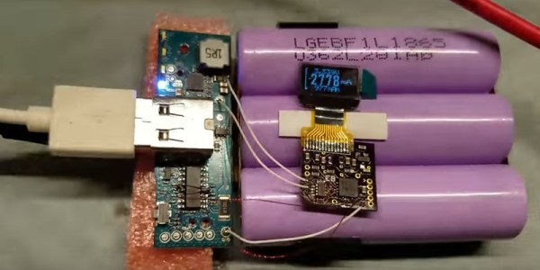
Inside the bulk of this power bank are an eye-popping 64 18650 Lithium Ion cells, mostly collected from laptop batteries, and wired in a parallel 8×8 pattern with an estimated capacity of over 100,000mAh(!!).  The gatekeeper to all this stored energy is a two-USB power bank charger board from Tindie.

Ah — but how to package all this power? The handy man’s secret weapon: duct-tape!

Continue reading “Monstrous USB Power Bank”

Playing Mario On An Oscilliscope

Any display can be connected to a microcontroller and used as a display if you know the protocol to use and have enough power in your micro. Sometimes, an odd display is used just “because it’s there.” This seems to be the case for Reddit user [phckopper], who has used a STM32 and a PS2 joystick to play a version of a Mario game on an oscilloscope.

There’s not many technical details but [phckopper] lets us know that the rendering is done using the SPI on the STM, transferred via DMA, which is synchronized to two saw-tooth waves that are fed in to the X and Y axes of the oscilloscope.  The Z axis, which controls the brightness of the dot, is fed from the MOSI. By making the oscilloscope range all over the screen, similar to the way a CRT’s gun does, [] is able to draw sprites, rather than vector graphics. The display has a resolution of 400×400 and each sprite is 16×16. The input is from a PS2 joystick connected to [phckopper]’s PC, with the information communicated over UART using a simple protocol.

We don’t get to see much of the game in the video after the break, but it’s a pretty impressive job nonetheless, especially when you realize that [phckopper] did this project when he was just sixteen! There are a couple of other oscilloscope projects here at Hackaday, like this one, a great version of pong played on the ‘scope, or this one, showing off some great graphics.

Continue reading “Playing Mario On An Oscilliscope”

Quick And Dirty Blimp Mount For A Shotgun Mike

Sometimes you don’t have the hardware you need, and you can either do without or let the project’s needs inspire you to create an alternative. That’s pretty sweet, and it’s even sweeter when you find a solution that’s dirt cheap.

[Chu_st] created a sub-$10 blimp mount for his shotgun mike. It consists of a PVC pipe which attaches to the microphone’s shock mount. Plastic gardening grid is used for the shell, shaped by hand into the desired blimp shape and secured with zip ties and gaffer tape. [Chu_st] suggests using nylon stocking as a wind screen. The microphone itself attaches to a length of bicycle seat tube using a standard mic clamp.

For DIY microphone projects, we got you covered, with everything from a low noise floor microphone to one built out of a hard drive published previously.

Building This TARDIS Is Anything But A Snap

As an avid fan of the show Dr Who, [Adam Sifounakis] saw a model for a laser-cut TARDIS that piqued his curiosity that eventually grew into a multi-week project involving multiple setbacks, missteps, revamps and — finally — gratification. Behold, his sound activated TARDIS.

First and foremost, assembling and painting the model was a fun puzzle — despite a few trips to the store — with a little backtracking on the painting due to impatience. Next, the creation of a pulsing soft white LED circuit timed with an audio clip to really sell the image of a mini-TARDIS proved to be a tedious ordeal, paying off in the end with a satisfying glow through the vellum-diffused windows on the model.

How to trigger the lights? [Sifounakis] initially wanted a capacitive sensor to trigger the sound effects, but that way lay dragons — and madness — so he went with snap-activated effect to activate the TARDIS like the Doctor himself. After struggling with building his own microphone setup, he switched to an electret mic with adjustable gain which worked like a charm. Setting up this TARDIS’ Adafruit Pro Trinket brain involved a snag or two, and after that it was smooth sailing!

Until he hit another hitch with the power circuit too, that is. Luckily enough, adding a capacitor to give the circuit a bit more juice on boot solved the issue. All that was left to do was dismantle and rebuild his circuit after all this troubleshooting and substitutions, and — finally — install it in his model.

With much satisfaction and a final rework of the LED pulsing effect, it was done. Check it out!

Continue reading “Building This TARDIS Is Anything But A Snap”

Scooter Wheels Keep DIY Barn Doors On Track

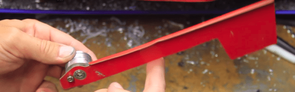
[MotoGeeking] built a giant spray booth and is in the process of making customized, air-filtering barn doors for it. When it came to buy hardware to move the doors, though, he found all the ready-made options to be prohibitively expensive. You know what comes next: he designed barn door hardware from the ground up, and did it as cheaply as possible.

After intensely studying many images of barn doors and hardware, [MotoGeeking] decided on the right wheels and went from there. Kick scooter wheels fit the bill nicely, since they are designed to support a lot of weight and come with their own bearings and spacers. And they’re cheap, too — just $9 for a pair.

[MotoGeeking] found some C channel extruded aluminium that seemed to be a perfect match for the wheels, but the wheel was quick to bind whenever it touched the sides. He solved that one by epoxying a length of round bar into the bottom corners. This allows the wheel to move freely while forcing it to stay centered in the track.

In designing the 1/4″ aluminium brackets, [MotoGeeking] took a measure thrice, order once approach to selecting the fasteners. You probably know by now that McMaster-Carr has free CAD drawings for every little thing. [MotoGeeking] imported the ones he liked into Illustrator and built around them. This helped him get it right the first time and kept the headaches and hair-tearing away. Watch the giant door skeleton glide effortlessly on its track after the break.

Continue reading “Scooter Wheels Keep DIY Barn Doors On Track”

Knitting ALUs (and Flipdots)

[Irene Posch] is big into knitted fabric circuits. And while most of the textile circuits that we’ve seen are content with simply conducting enough juice to light an LED, [Irene]’s sights are set on knittable crafted arithmetic logic units (ALUs). While we usually think of transistors as the fundamental building-blocks of logic circuits, [Irene] has developed what is essentially a knit crochet relay. Be sure to watch the video after the break to see it in construction and in action.

The basic construction is a coil of conductive thread that forms an electromagnet, and a magnetic bead suspended on an axle so that it can turn in response to the field. To create a relay, a flap of knit conductive thread is attached to the bead, which serves as the pole for what’s essentially a fabric-based SPDT switch. If you’ve been following any of our relay-logic posts, you’ll know that once you’ve got a relay, the next step to a functioning computer is a lot of repetition.

How does [Irene] plan to display the results of a computation? On knit-and-bead flipdot displays, naturally. Combining the same electromagnet and bead arrangement with beads that are painted white on one side and black on the other yields a human-readable one-bit display. We have an unnatural affinity for flipdot displays, and making the whole thing out of fabric-store components definitely flips our bits.

Anyway, [Irene Posch] is a textile-tech artist who you should definitely be following if you have any interest in knittable computers. Have you seen anything else like this? Thanks [Melissa] for the awesome tip!

Continue reading “Knitting ALUs (and Flipdots)”