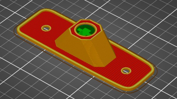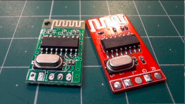
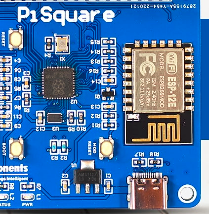
We have all seen Printed Circuit Board (PCB) antennas: those squiggly bits of traces on PCBs connected often to a Bluetooth, WiFi or other wireless communication chip. On modules like for the ESP8266 and ESP32 platforms the PCB antennas are often integrated onto the module’s PCB, yet even with such a ready-made module it’s possible to completely destroy the effectiveness of this antenna. These and other design issues are discussed in this article by [MisterHW].
It covers a range of examples of poor design, from having ground fill underneath an antenna, to having metal near the antenna, to putting dielectric materials near or on top of the antenna. The effect of all of these issues is generally to attenuate the signal, sometimes to the point where the antenna is essentially useless.
Ultimately, the best PCB antenna design is one where there is no nearby copper fill, and there are no traces running near or on layers below the antenna. After all, any metal trace or component is an antenna, and any dielectric materials will dampen the signal. Fortunately, there is e.g. a free KiCad library with ready-to-use PCB antenna designs to help one get started with a custom design, as well as many other resources, covered in the article.
If you want to get really professional about checking the effectiveness of an antenna design, you’ll want to use a Network Vector Analyzer. These will also help you with tuning the capacitors used with the PCB antenna.
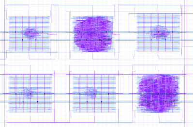
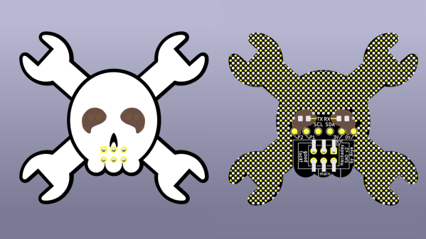
(Featured image: PCB antenna rendered useless by overly enthusiastic copper fill.)
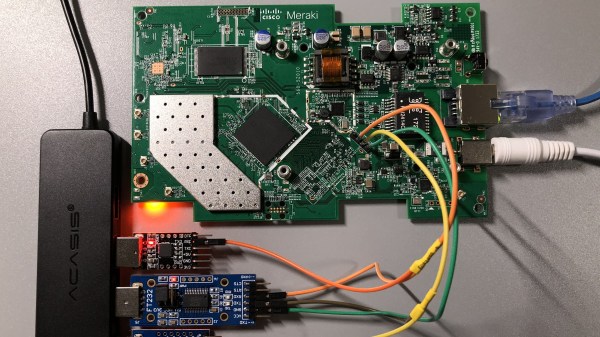
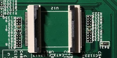 The flash chip is in TSOP48 package and uses a parallel interface, and an iMX6.LL devboard was used to read, modify and flash back the image — hotswapping the chip, much like we used to do with old parallel-interface BIOS chips. We especially liked the use of FFC cables and connectors for connecting the flash chip to the devboard in a way that allows hotswapping – now that we can see it, the TSOP 0.5 mm pitch and 0.5 mm FFC hardware are a match made in heaven. This hack, of course, will fit many TSOP48-equipped devices, and it’s nice to have a toolkit for it in case you don’t have a programmer handy.