For a little over a year now we’ve been covering the incredible replicas [Mike Gardi] has been building of educational “computers” from the very dawn of the digital age. These fascinating toys, many of which are now extremely rare, are recreated using 3D printing and other modern techniques for a whole new generation to enjoy and learn from.
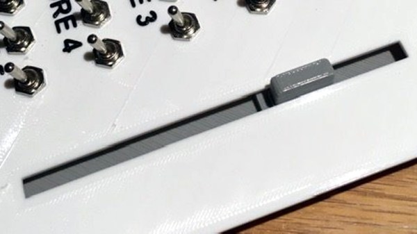
He’s picked up a trick or two building these replicas, such as this method for creating bespoke slide switches with a 3D printer. Not only does this idea allow you to control a custom number of devices, but as evidenced in the video after the break, the printed slider sounds absolutely phenomenal in action. Precisely the sort of “clunk” you want on your front panel.
Of course, [Mike] doesn’t expect anyone to create this exact switch. He’s designed it as part of his Working Digital Computer (WDC-1) project that he’s documenting on Hackaday.io, so it has a rather specific set of design parameters. But with the steps he outlines in the write-up, you should have no problem adapting the concept to fit your specific needs.


So how does it work? One half of the switch is a track is printed with indents for both reed switches and 6 x 3 mm disc magnets. The other is a small shuttle that itself has spaces for two of the same magnets. When it slides over the reed switches they’re activated by the magnet on one side, while the magnet on the other side will be attracted to the one embedded into the track. This not only gives the switch detents that you can feel and hear while moving it, but keeps the shuttle from sliding off the intended reed switch.
If you like this, you’ll absolutely love his mostly 3D printed binary encoder that we featured recently. With his track record, we’re excited to follow the WDC-1 project as it develops, and thrilled that [Mike] has brought it to Hackaday.io.