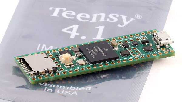
3D Printed Swirl Rocket Injector Turns Up The Heat

Conceptually speaking, a liquid propellant rocket engine is actually a very simple piece of hardware. All you need to do is spray your fuel and oxidizer into the combustion chamber at the proper ratio, add a spark, and with a carefully designed nozzle you’re off to the races. Or the Moon, as the case may be. It’s just that doing it in the real-world and keeping the whole thing from exploding for long enough to do some useful work is another story entirely.

Taking the process one step at a time, [Luke Walters] has been working on a 3D printed injector that tackles the first half of the problem. After nearly a dozen different prototypes, he’s come up with a printable injector design that atomizes the fuel and combines it with pressurized air at a suitable ratio for combustion. As you can see in the video at the break, it’s certainly capable of generating some impressive fireballs.

A cloud of highly atomized alcohol from the injector.

The internal passages of the injector have been designed in such a way that fuel (91% isopropyl alcohol) and air are spinning in opposite directions when they meet. This promotes more complete mixing, which in turn leads to a more efficient burn. Originally developed in the 1930s, so-called “swirl injectors” of this type were one of the key technological advancements made by Germany’s V-2 rocket program. Some ideas never go out of style.

Since the injector only touches the fuel and air prior to ignition, it doesn’t need to be particularly heat resistant. To be on the safe side [Luke] has printed the part in PETG at 100% infill, but in reality the flame front is far enough away that temperature isn’t much of a concern. That said, he does hope to eventually fit these injectors into some kind of combustion chamber, which is where things will start getting toasty.

To be clear this is not a rocket engine, and it produces no appreciable thrust. Turning a big flame into a useful means of propulsion is where things get tricky, almost as though it’s rocket science or something. But that doesn’t mean it can’t be done by suitably ambitious hackers.

Continue reading “3D Printed Swirl Rocket Injector Turns Up The Heat”

Forming Sheet Metal Parts With 3D Printed Dies

Using 3D printed forms to bend sheet metal isn’t exactly new. We’ve seen several people create custom dies for their brakes, and the results have shown the concept has merit for small-scale production. But that’s usually where the process ends. A bend here or there is one thing, but the ability to form a complex shape with them has always seemed like asking too much. But judging by his recent experiments, [Shane Wighton] is very close to changing that perception.

The process at work here is, relatively speaking, pretty simple. You print out the upper and lower die, put a piece of sheet metal between them, and then smash them together with a hydraulic press. If everything works correctly, and your CAD skills hold true, the metal will take the desired shape.

Of course, that’s vastly oversimplifying things. As [Shane] explains in the video after the break, there are many nuances to forming sheet metal like this that need to be taken into account, and iteration and experimentation are basically unavoidable. So it’s a good thing you can rapidly redesign and reprint the dies.

Which isn’t to say that the dies themselves didn’t come with their own unique set of challenges. The first ones shattered under the pressure, and it took a few design revisions and eventually a switch to a stronger resin before [Shane] got a set of dies that could form the desired piece. Even still, he’s had a lot of trouble getting the printed parts to survive multiple uses. But he’s confident with some more refinements he could get a repeatable process going, and thinks ultimately producing runs of up to 100 parts on a set of printed dies isn’t out of the question.

Logically, it would seem plastic isn’t an ideal choice for punching and shaping metal. Frankly, it’s not. But if you’re doing in-house manufacturing, the ability to produce complex tooling quickly and easily can help make up for any downsides it might have.

Continue reading “Forming Sheet Metal Parts With 3D Printed Dies”

Multi-Band Receiver On A Chip Controlled By Arduino

The Silicon Labs Si4735 is a single-chip solution for receiving AM, FM, and shortwave radio. With a bit of hacking, it even supports single sideband (SSB). All you’ve got to do is provide it with a suitable control interface, which [Ricardo Lima Caratti] has done with his recent project.

Using an Arduino Pro Mini, a handful of buttons, and a standard TFT display, [Ricardo] has put together a serviceable little receiver with a fairly impressive user interface. We especially like the horizontal bars indicating the signal to noise ratio and received signal strength. The next evolution would be to put this whole rig into some kind of enclosure, but for now he seems content to control the action with a handful of unlabeled buttons on a piece of perfboard.

Of course, the presentation of this receiver isn’t really the point; it’s more of a proof of concept. You see, [Ricardo] is the person who’s actually developed the library that allows you to control the Si4735 from your microcontroller of choice over I2C. He’s currently tested it with several members of the official (and not so official) Arduino family, as well as the ESP32.

The documentation [Ricardo] has put together for his MIT licensed Arduino Si4735 library is nothing short of phenomenal. Seriously, if all open source projects were documented even half as well as this one is, we’d all be a few notches closer to world peace. Even if you aren’t terribly interested in adding shortwave radio reception to your next project, you’ve got to browse his documentation just to see where the high water mark is.

We actually first heard about this library a few days ago when we covered another receiver using the Si4735 and [Ricardo] popped into the comments to share some of the work he’d been doing to push the state-of-the-art forward for this promising chip.

Continue reading “Multi-Band Receiver On A Chip Controlled By Arduino”

Solid State Relay Simulation, Explained

[SaltyPuglord] needed a solid state relay for a project. We’d have just bought one, but he decided to design his own in LTSpice. Along the way he made the video below, which is pretty informative and a good example of a non-trivial design in LTSpice.

MOSFETs have made designs like this a lot easier, to the extent that it should be as easy as putting a pair of beefy fets in-line with the AC source and load. However, that has a few ramifications that [Salty] covers in the video.

The biggest concern comes in isolating the DC supply from ground. He used a transformer which is tricky to simulate in LTSpice. Beyond that the design of the power supply is quite simple, and as he mentions in the video, you don’t really need this complex of a regulator just to feed the gates of the MOSFETs.

Continue reading “Solid State Relay Simulation, Explained”

The TMS1000: The First Commercially Available Microcontroller

We use a microcontroller without a second thought, in applications where once we might have resorted to a brace of 74 logic chips. But how many of us have spared a thought for how the microcontroller evolved? It’s time to go back a few decades to look at the first commercially available microcontroller, the Texas Instruments TMS1000.

Imagine A World Without Microcontrollers

The Texas Instruments Speak And Spell from 1978 was a typical use for the TMS1000.
The Texas Instruments Speak & Spell from 1978 was a typical use for the TMS1000. FozzTexx (CC-SA 4.0)

It’s fair to say that without microcontrollers, many of the projects we feature on Hackaday would never be made. Those of us who remember the days before widely available and easy-to-program microcontrollers will tell you that computer control of a small hardware project was certainly possible, but instead of dropping in a single chip it would have involved constructing an entire computer system. I remember Z80 systems on stripboard, with the Z80 itself alongside an EPROM, RAM chips, 74-series decoder logic, and peripheral chips such as the 6402 UART or the 8255 I/O port. Flashing an LED or keeping an eye on a microswitch or two became a major undertaking in both construction and cost, so we’d only go to those lengths if the application really demanded it. This changed for me in the early 1990s when the first affordable microcontrollers with on-board EEPROM came to market, but by then these chips had already been with us for a couple of decades.

It seems strange to modern ears, but for an engineer around 1970 a desktop calculator was a more exciting prospect than a desktop computer. Yet many of the first microcomputers were designed with calculators in mind, as was for example the Intel 4004. Calculator manufacturers each drove advances in processor silicon, and at Texas Instruments this led to the first all-in-one single-chip microcontrollers being developed in 1971 as pre-programmed CPUs designed to provide a calculator on a chip. It would take a few more years until 1974 before they produced the TMS1000, a single-chip microcontroller intended for general purpose use, and the first such part to go on sale. Continue reading “The TMS1000: The First Commercially Available Microcontroller”

Transparent LCD Makes Everything Look Futuristic

According to [Kelsey], transparent displays are guaranteed to make “everything feel like the future.” Unfortunately they’re hard to find, and the ones typically available are OLED and can’t make solid black colors. But as luck would have it, it’s possible to repurpose a common LCD to be sort of transparent.

A LCD uses nematic crystals that can polarize light, with the amount of polarization changing based on the electric field applied to the crystal. Light enters the front of the panel through a polarizing film, passes through the display, and then bounces off a reflective back coating. The display itself usually polarizes light in a way that matches the front polarizer. That means if you do nothing you get reflected light. However, if a part of the LCD gets an electric field, it will repolarize in such a way as to block the reflected light making the display look black in that area.

[Kelsey’s] trick is to peel off the reflector and replace it with polarizing film taken from another display. The new polarizer needs to be bigger than the display for one reason: you need to match the polarizing angle of the front film with the new back film. That means if the new film is exactly the right size, it won’t be able to rotate without leaving gaps. By starting with a larger piece, you’ll be able to rotate for maximum transparency before you stick it on.

We’ve seen some homemade transparent numeric displays. The transparent wood, though, has usually left something to be desired.

Why Some Chips Have Inconvenient Pinouts

If you’ve ever handled a chip with a really strange or highly inconvenient pinout and suspected that the reason had something to do with the inner workings, you may be interested to see [electronupdate]’s analysis of why the 4017 Decade Counter IC has such a weirdly nonintuitive pinout. It peeks into an IC design dating from the 1970s to see an example of the kind of design issues that can affect physical layout.

Inside the 4017. Want to make sense of how lines and shapes on a silicon wafer make an IC work? With the right teachers, it’s simple.

In the case of the 4017, once decapped and the inner workings exposed, things became more clear. Inside the chip are a bunch of flip-flops and NAND gates, laid out in a single layer. Some of the outputs (outputs 5 and 1 for example, physically on pins 1 and 2 respectively) share the same flip-flop.

The original design placed the elements in a way that made the most logical sense for routing and layout, which resulted in nice and tidy inner workings but an apparently illogical pinout. A lot of this is probably feeling familiar to anyone who has designed and routed a single-layer PCB, where being limited to one layer makes it important to get the most connections as directly near one another as possible.

Chip design has of course come a long way since the 70s, but there is forever some level of trade-off to be made between outward tidiness and inner design harmony. The next time you’re looking at a part with an apparently illogical pinout, there’s a fair chance it makes far more sense on the inside.

If any of you are interested in decapping ICs yourselves to see what’s inside, we saw that it’s possible with commonly available chemicals, not just nasty ones.

Continue reading “Why Some Chips Have Inconvenient Pinouts”