Sega’s Game Gear Gets A Video Output

[EvilTim] dug deep into a classic system to finally give the Game Gear a proper video output.  The Game Gear was Sega’s answer to Nintendo’s Gameboy. Rushed to market, the Game Gear reused much of the hardware from the very popular Master System Console. The hardware wasn’t quite identical though – especially the cartridge slot. You couldn’t play Game Gear games on a Master System, and the game gear lacked an AV output, which meant gamers were stuck playing on a small fluorescent backlit LCD screen.

[EvilTim] wanted to play some of those retro titles on a regular TV using the original hardware. To accomplish this he had to start digging into the signals driving the Game Gear’s LCD. The Master System lineage was immediately apparent, as Game Gear’s LCD drive signals were similar in timing to those used to drive a TV. There was even a composite sync signal, which was unused on in the Game Gear.

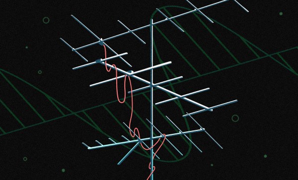
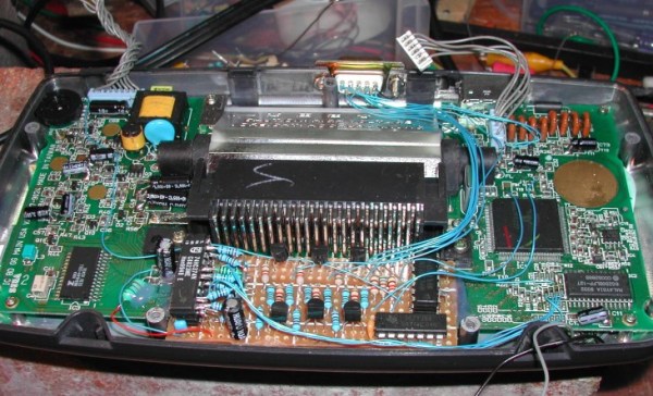
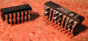
[EvilTim] first designed a circuit using discrete ’74 series logic which would convert the LCD drive signals to SCART RGB. Of note is the construction technique used in this circuit. A tower of three 74HC374 chips allows [EvilTim] to create R, G, and B outputs without the need for a complex circuit board.

As pretty as a three-story chip tower is, [EvilTim] knew there was a better way. He re-spun the circuit with a 32 macrocell CPLD. This version also has an NTSC and PAL video encoder so those without a SCART interface can play too. If you’re not up to building your own, [EvilTim] sells these boards on his website.

We’ve seen some incredible retro gaming hacks over the years. From a NES inside a cartridge to incredible RetroPi builds. Hit the search bar and check it out!

Ohm? Don’t Forget Kirchhoff!

It is hard to get very far into electronics without knowing Ohm’s law. Named after [Georg Ohm] it describes current and voltage relationships in linear circuits. However, there are two laws that are even more basic that don’t get nearly the respect that Ohm’s law gets. Those are Kirchhoff’s laws.

In simple terms, Kirchhoff’s laws are really an expression of conservation of energy. Kirchhoff’s current law (KCL) says that the current going into a single point (a node) has to have exactly the same amount of current going out of it. If you are more mathematical, you can say that the sum of the current going in and the current going out will always be zero, since the current going out will have a negative sign compared to the current going in.

You know the current in a series circuit is always the same, right? For example, in a circuit with a battery, an LED, and a resistor, the LED and the resistor will have the same current in them. That’s KCL. The current going into the resistor better be the same as the current going out of it and into the LED.

This is mostly interesting when there are more than two wires going into one point. If a battery drives 3 magically-identical light bulbs, for instance, then each bulb will get one-third of the total current. The node where the battery’s wire joins with the leads to the 3 bulbs is the node. All the current coming in, has to equal all the current going out. Even if the bulbs are not identical, the totals will still be equal. So if you know any three values, you can compute the fourth.

If you want to play with it yourself, you can simulate the circuit below.

The current from the battery has to equal the current going into the battery. The two resistors at the extreme left and right have the same current through them (1.56 mA). Within rounding error of the simulator, each branch of the split has its share of the total (note the bottom leg has 3K total resistance and, thus, carries less current).

Continue reading “Ohm? Don’t Forget Kirchhoff!”

On Point: The Yagi Antenna

If you happened to look up during a drive down a suburban street in the US anytime during the 60s or 70s, you’ll no doubt have noticed a forest of TV antennas. When over-the-air TV was the only option, people went to great lengths to haul in signals, with antennas of sometimes massive proportions flying over rooftops.

Outdoor antennas all but disappeared over the last third of the 20th century as cable providers became dominant, cast to the curb as unsightly relics of a sad and bygone era of limited choices and poor reception. But now cheapskates cable-cutters like yours truly are starting to regrow that once-thick forest, this time lofting antennas to receive digital programming over the air. Many of the new antennas make outrageous claims about performance or tout that they’re designed specifically for HDTV. It’s all marketing nonsense, of course, because then as now, almost every TV antenna is just some form of the classic Yagi design. The physics of this antenna are fascinating, as is the story of how the antenna was invented.

Continue reading “On Point: The Yagi Antenna”

First Look At ABC: Basic Connections

[Alberto Piganti], aka [pighixxx] has been making circuit diagram art for a few years now, and has just come out with a book that’s available on Kickstarter. He sent us a copy to review, and we spent an hour or so with a refreshing beverage and a binder full of beautiful circuit diagrams. It doesn’t get better than that!

[pighixxx] started out making very pretty and functional pinout diagrams for a number of microcontrollers, and then branched out to modules and development boards like the Arduino and ESP8266. They’re great, and we’ll admit to having a printout of his SMD ATMega328 and the ESP-12 on our wall. His graphical style has been widely copied, which truly is the sincerest form of flattery.

But after pinouts, what’s next? Fully elaborated circuit diagrams, done in the same style, of course. “ABC: Basic Connections” started out life as a compendium of frequently used sub-circuits in Arduino projects. But you can take “Arduino” with a grain of salt — these are all useful for generic microcontroller-based projects. So whether you want to drive a 12 V solenoid from a low-voltage microcontroller, drive many LEDs with shift registers, or decode a rotary encoder, there is a circuit snippet here for you. Continue reading “First Look At ABC: Basic Connections”

The Textile Bench

What’s on your bench? Mine’s mostly filled with electronic test equipment, soldering kit, and computers. I’m an electronic engineer by trade when I’m not writing for Hackaday, so that’s hardly surprising. Perhaps yours is like mine, or maybe you’ve added a 3D printer to the mix, a bunch of woodworking tools, or maybe power tools.

So that’s my bench. But is it my only bench? On the other side of the room from the electronics bench is a sturdy folding dining table that houses the tools and supplies of my other bench. I’m probably not alone in having more than one bench for different activities, indeed like many of you I also have a messy bench elsewhere for dismantling parts of 1960s cars, or making clay ovens.

My textile bench, with a selection of the equipment used on it.

The other bench in question though is not for messy work, in fact the diametric opposite. This is my textile bench, and it houses the various sewing machines and other equipment that allow me to tackle all sorts of projects involving fabric. On it I’ve made, modified, and repaired all sorts of clothing, I’ve made not-very-successful kites, passable sandals, and adventurous tent designs among countless other projects.

Some of you might wonder why my textile bench is Hackaday fodder, after all it’s probably safe to assume that few readers have ever considered fabricating their own taffeta ball gown. But to concentrate only on one aspect of textile work misses the point, because the potential is there for so much cross-over between these different threads of the maker world. So I’m going to take you through my textile bench and introduce you to its main tools. With luck this will demystify some of them, and maybe encourage you to have a go.

Continue reading “The Textile Bench”

Josef Prusa: Multi Material Extruders For Amazing Color Prints

The Prusa i3 Mk 2 is the hotness in consumer-grade, quality 3D printing right now. And things just keep getting more interesting. We caught up with Josef Průša at Maker Faire Bay Area this weekend to see the multi-material extruder in its final form. It’s an upgrade to the Mk 2 which allows a single hot end to print in four different materials, be it different colors or different types of filament.

Continue reading “Josef Prusa: Multi Material Extruders For Amazing Color Prints”

Doomed Thermostat

It is amazing how the game Doom has been ported to so many things. Enter one more port, where the hardware in question is a Honeywell Prestige thermostat.

In his video, [cz7asm] shows us the game running quite nicely on the 480 x 272 LCD with an NES controller plugged into the USB port originally intended for software updates. The thermostat runs on a STM32F429 which is an ARM9 processor that has the juice to pull it off. The Doom engine being used is based on Chocolate Doom, an open source port of the game, and the binaries can be downloaded for Windows and Mac. The source code is also available as a download for your tinkering pleasure. This project by [cz7asm]  is extended from a code on GitHub by [floppes] that was meant for the STM32F429IDISCOVERY evaluation board.

The author shares his code for the STM32F4 on Dropbox as a zip and in order to compile it, the Atmel BSP for GNU GCC is used. The video below demonstrates the hack in action and, though there is no sound yet, the satisfaction that comes from such modifications is its own reward.

What else can you run Doom on? How about a calculator or maybe the Intel Edison or even an ATM machine! If there is a processor with enough muscle power, hackers will find a way to run Doom on it. So have you seen any alien computers lately that you think can be hacked? Continue reading “Doomed Thermostat”