It is hard to get very far into electronics without knowing Ohm’s law. Named after [Georg Ohm] it describes current and voltage relationships in linear circuits. However, there are two laws that are even more basic that don’t get nearly the respect that Ohm’s law gets. Those are Kirchhoff’s laws.
In simple terms, Kirchhoff’s laws are really an expression of conservation of energy. Kirchhoff’s current law (KCL) says that the current going into a single point (a node) has to have exactly the same amount of current going out of it. If you are more mathematical, you can say that the sum of the current going in and the current going out will always be zero, since the current going out will have a negative sign compared to the current going in.
You know the current in a series circuit is always the same, right? For example, in a circuit with a battery, an LED, and a resistor, the LED and the resistor will have the same current in them. That’s KCL. The current going into the resistor better be the same as the current going out of it and into the LED.
This is mostly interesting when there are more than two wires going into one point. If a battery drives 3 magically-identical light bulbs, for instance, then each bulb will get one-third of the total current. The node where the battery’s wire joins with the leads to the 3 bulbs is the node. All the current coming in, has to equal all the current going out. Even if the bulbs are not identical, the totals will still be equal. So if you know any three values, you can compute the fourth.
If you want to play with it yourself, you can simulate the circuit below.
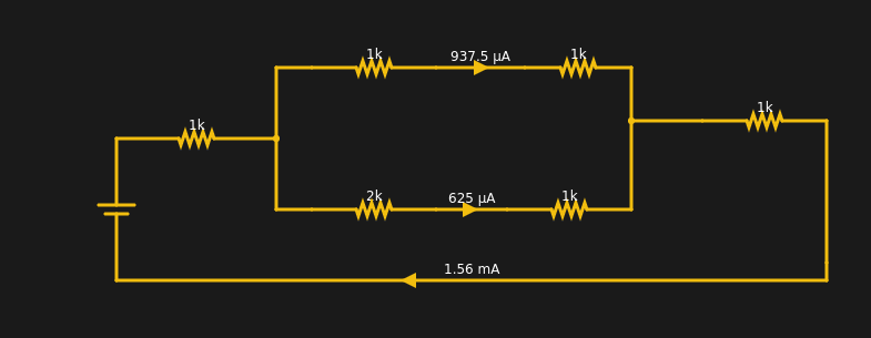
The current from the battery has to equal the current going into the battery. The two resistors at the extreme left and right have the same current through them (1.56 mA). Within rounding error of the simulator, each branch of the split has its share of the total (note the bottom leg has 3K total resistance and, thus, carries less current).
Continue reading “Ohm? Don’t Forget Kirchhoff!” →


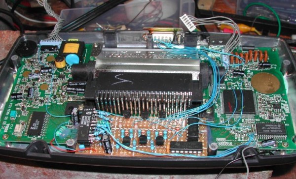
 [EvilTim] first designed a circuit using discrete ’74 series logic which would convert the LCD drive signals to SCART RGB. Of note is the construction technique used in this circuit. A tower of three 74HC374 chips allows [EvilTim] to create R, G, and B outputs without the need for a complex circuit board.
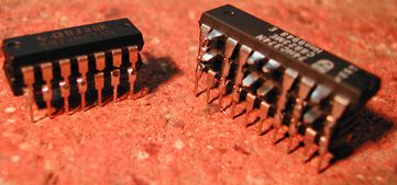