The Raspberry Pi Foundation founder Eben Upton has revealed in an interview with PCWorld that there will be a new version of the organisation’s Compute Module featuring the faster processor from the latest Raspberry Pi 3 boards, and it will be available “In a few months”.
The Compute Module was always something of an odd one out among the Raspberry Pi range, being a stripped-out Raspberry Pi chipset on a SODIMM form factor card without peripherals for use as an embedded computer rather than the standalone card with all the interfaces we are used to in the other Pi boards. It has found a home as the unseen brains behind a selection of commercial products, and though there are a few interface boards for developers and experimenters available for it we haven’t seen a lot of it in the world of hackers and makers. Some have questioned its relevance when the outwardly similar Pi Zero can be had for a lower price, but this misses the point that the two boards have been created for completely different markets.
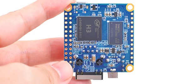
The Pi 3’s 1.2 GHz 64-bit quad-core ARM Cortex-A53 BCM2837 SoC will certainly up the ante in the Compute module’s market, but it will be interesting to see what changes if any they make to its form factor. The Foundation’s close ties with Broadcom mean that they have done an impressive job in maintaining backward compatibility at a hardware level between the different generations of their product, but it is unclear whether this extends to the possibility of the new module maintaining a pin-for-pin compatibility with the old. We’d expect this to be an unlikely prospect.
It is certain that we will see a new generation of exciting commercial products emerging based around the new module, but will we see it making waves within our domain? This will depend on its marketing, and in particular the price point and quantity purchase they set for it. The previous board when added to a Compute Module Development board was an expensive prospect compared to a Raspberry Pi Model B that became more unattractive still as newer Pi boards gained more capabilities. If they price this one competitively and perhaps if any cheaper open hardware breakout boards emerge for it, we could have a valuable new platform on our hands.
Here’s our coverage of the original Compute Module launch, back in 2014.
[via Liliputing and reddit].
BCM2837 image: By Jose.gil (Own work) [CC BY-SA 4.0], via Wikimedia Commons.