Arduino SRL (formerly known as Smart Projects SRL) sent out a letter to its distribution partners yesterday. If you’ve been following along with the Arduino vs Arduino story (we’ve previously published two installments), the content isn’t entirely surprising; it’s essentially a tactical move to reassure their distribution channels that Arduino SRL is the “One True Arduino”. That said, there’s still some new tidbits buried inside. You can skip down to read the full text below, but here’s our take.
The Business History of Arduino
 A quick summary of the legal situation. Arduino LLC was formed in April 2008 by the original five founders to provide a corporate entity behind the Arduino project. Smart Projects SRL, controlled by one of the founders, was tasked with the actual production of the boards. It turns out that Smart Projects had trademarked the Arduino brand in Italy in December 2008, before Arduino LLC got around to filing in April 2009 in the USA. But everyone was friends, right? As long as the licensing fees keep flowing.
Fast-forward to September 2014, when Arduino LLC filed a lawsuit in Italy against Smart Projects claiming that they had infringed LLC’s trademark and that they had recently stopped paying licensing fees on their use of the Arduino name. In October, Smart Projects filed with the USPTO to revoke Arduino LLC’s trademark. In late 2014, Smart Projects changed its company name to Arduino SRL (a “Società a responsabilità limitata” is one form of Italian limited-liability company) and hired a new CEO, [Federico Musto]. Around the same time, Arduino SRL opened up the website arduino.org (different from long-existing arduino.cc) but with nearly identical style. In January 2015, Arduino LLC filed a lawsuit in the US, claiming their right on the Arduino name.
The Gist of it
In short, Arduino LLC has been working on developing the Arduino platform, software, and community while Smart Projects / Arduino SRL was the major official producer of the hardware for most boards. Both are claiming to “be” Arduino, and going after each other in court. So it’s not strange that Arduino SRL would like to try to keep its hold on the distribution channels. Which brings us to their letter to distributors.
March 27 Letter
 A good portion of the letter reads to be a very carefully worded defense of why Arduino SRL is the true Arduino:
“Arduino Srl (aka Smart Projects Srl), as you know has been from the beginning of the Arduino® project, the place where the ideas were turned into reality and into a business.”
This is of course strictly true — Smart Projects was certainly the largest manufacturer of Arduino boards. But it sidesteps the issue at hand in the trademark suits: whether they were simply a licensed producer of the boards or whether they’re “Arduino”.
Similarly, in the questions section of the letter, they ask if there are actually two “Arduino” product manufacturers, and answer “not really”. Of course, that’s true. Arduino LLC doesn’t manufacture boards, but exists to license their trademark out to fund development.
The only real news in the letter is that Arduino SRL is replacing its old distribution and logistics company, Magyc Now, with a new one named CC Logistics. Both Magyc and CC Logistics are named as defendants in the US lawsuit filed by Arduino LLC, so it’s unlikely that this change is due to legal fallout.
What this Means
In conclusion, Arduino SRL’s letter to its distributors seems to essentially follow the line of reasoning in their trademark lawsuit in the US against Arduino LLC: since Arduino SRL is doing the manufacturing and using the Arduino name, they’re the true Arduino. Whether or not this will stand up in court, or whether Arduino LLC can make its case that SRL was simply a licensed manufacturer, remains to be seen.
We’ve embedded the contents of the letter after the break. You can also download the original PDF.
Continue reading “Arduino SRL To Distributors: “We’re The REAL Arduino””
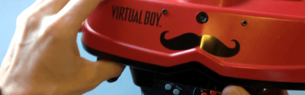
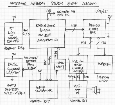 I was selling a bunch of my video game collection at PRGE (Portland Retro Gaming Expo) a few years ago and had a broken Virtual Boy that no one bought. A friend of mine was at the table and said I had to do something with it. I thought “People wear cosplay and walk around at conventions, so what if I could do something with the Virtual Boy that you could walk around with?” That was the seed.
 I saw a TI BeagleBoard demo called “
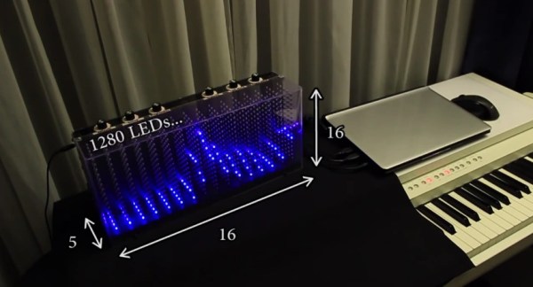
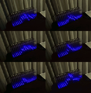 When [Dooievriend] set out to design the audio analyzing portion of the firmware, his mind jumped to the discrete Fourier transform. This transform calculates the amplitude in a series of frequency bins in the audio—seemingly perfect for a VU. However, after some more research, [Dooievriend] decided to implement a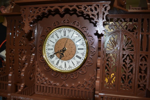
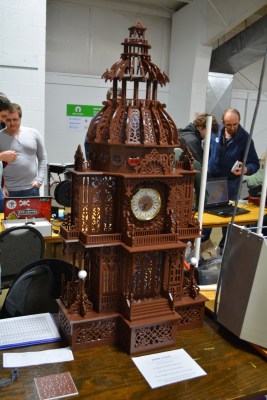 As you might imagine, a great deal of work went into this build, beginning with the scanning. [Jason] starting scanning last October and finished in January. Printing started January 9th, and he told me the final pieces were printed early this morning. We know you want all the details, so here goes: this build took just over six rolls of PLA at 20% infill. It’s 48″ tall and about 24″ wide. It was printed on what [Jason] referred to as his “very modified” Replicator 2. He glued the pieces together with Testor’s, and that took about 30 hours. All through the project, he kept meticulous notes in a spreadsheet of print times and filament used.