Someone setting down an arUco tag

Make Your Own Virtual Set

An old adage says out of cheap, fast, and good, choose two. So if you’re like [Philip Moss] and trying to make a comedy series on a limited budget rapidly, you will have to take some shortcuts to have it still be good. One shortcut [Philip] took was to do away with the set and make it all virtual.

If you’ve heard about the production of a certain western-style space cowboy that uses a virtual set, you probably know what [Philip] did. But for those who haven’t been following, the idea is to have a massive LED wall and tracking of where the camera is. By creating a 3d set, you can render that to the LED wall so that the perspective is correct to the camera. While a giant LED wall was a little out of budget for [Philip], good old green screen fabric wasn’t. The idea was to set up a large green screen backdrop, put some props in, get some assets online, and film the different shots needed. The camera keeps track of where in the virtual room it is, so things like calculating perspective are easy. They also had large arUco tags to help unreal know where objects are. You can put a wall right where the actors think there’s a wall or a table exactly where you put a table covered in green cloth.

Initially, the camera was tracked using a Vive tracker and LiveLink though the tracking wasn’t smooth enough while moving to be used outside of static shots. However, this wasn’t a huge setback as they could move the camera, start a new shot, and not have to change the set in Unreal or fiddle with compositing. Later on, they switched to a RealSense camera instead of the Vive and found it much smoother, though it did tend to drift.

The end result called ‘Age of Outrage’, was pretty darn good. Sure, it’s not perfect, but it doesn’t jump out and scream “rendered set!” the way CGI tv shows in the 90’s did. Not too shabby considering the hardware/software used to create it!

Monochrome LCD Video Hacks Galore!

[Wenting Zhang] is clearly a fan of old school STN LCD displays, and was wondering how various older portable devices managed to drive monochrome LCDs panels with multiple grey levels. If the display controller supports multiple bits per pixel, it can use various techniques, such as PWM, in order to produce a pseudo-grayscale image. But, what if you have a monochrome-only display controller? With a sufficiently high pixel clock, can you use software on the application side of things to flip those pixels in such a manner as to give a reasonable looking grayscale image?

Simple dithering – don’t look too close!
PDM greyscale approximation in a 1-bit display

[Wenting] goes through multiple techniques, showing the resulting image quality in a clear, systematic manner. The first idea is to use a traditional dithering technique. For each pixel, it is set to black if the grey value is below some threshold. The resulting error value, is then propagated to neighbouring pixels. This error diffusion process smears the error out over the whole display, so spatially speaking, on average the pixel values correspond roughly to the original gray values. But, the pixels themselves are still either on or off. This isn’t quite enough. The next idea is to PWM the individual pixels over multiple frames, to approximate different grey levels. But, that gives a worst case effective refresh rate of 8 Hz with a PWM period of 15 frames, at 120 fps, and that flickers. Badly. One way to mitigate that is to switch to PDM (pulse density modulation) which selects different length sequences to give the same duty cycle but at higher frequency, at least for some grey values. Slightly better, but there’s more that can be done. Continue reading “Monochrome LCD Video Hacks Galore!”

Retrotechtacular: How Television Worked In The 1950s

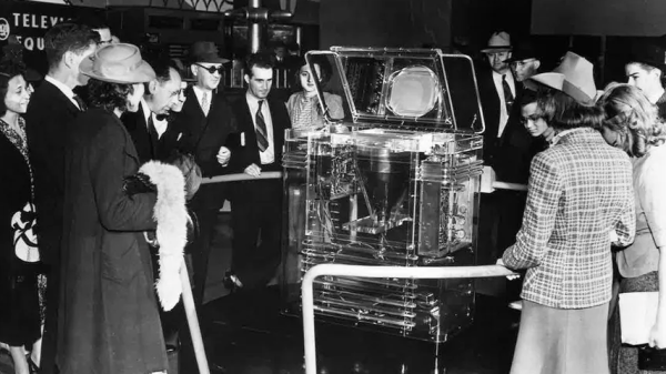
Watching television today is a very different experience from that which our parents would have had at our age, where we have high-definition digital on-demand streaming services they had a small number of analogue channels serving linear scheduled broadcasting. A particular film coming on TV could be a major event that it was not uncommon for most of the population to have shared, and such simple things as a coffee advert could become part of our common cultural experience. Behind it all was a minor miracle of synchronised analogue technology taking the signal from studio to living room, and this is the subject of a 1952 Coronet film, Television: How It Works!  Sit back and enjoy a trip into a much simpler world in the video below the break.

Filming a TV advert: 1950s housewife sells cooker
Production values for adverts had yet to reach their zenith in the 1950s.

After an introduction showing the cultural impact of TV in early-50s America there’s a basic intro to a cathode-ray tube, followed by something that may be less familiar to many readers, the Image Orthicon camera tube that formed the basis of most TV signals of that era.

It’s written for the general public, so the scanning raster of a TV image is introduced through the back-and-forth of reading a book, and then translated into how the raster is painted on the screen with the deflection coils and the electron gun. It’s not overly simplified though, for it talks about how the picture is interlaced and shows how a synchronisation pulse is introduced to keep all parts of the system working together.

A particularly fascinating glimpse comes in a brief mention of the solid copper co-axial cable and overland microwave links used to transmit TV signals across country, these concrete towers can still be seen today but they no longer have the colossal horn antennas we can see in the film.

A rather obvious omission in this film is the lack of any mention of colour TV, as while it would be late 1953 before the NTSC standard was formally adopted and early 1954 before the first few colour sets would go on sale. Colour TV would have been very much the Next Big Thing in 1952, but with no transmissions to watch and a bitter standards war still raging between the field-sequential CBS system and RCA’s compatible dot-sequential system that would eventually evolve into the NTSC standard  it’s not surprising that colour TV was beyond the consumer audience of the time.

Thus we’re being introduced to the 525-line standard which many think of as NTSC video, but without the NTSC compatible colour system that most of us will be familiar with. The 525-line analogue standard might have disappeared from our living rooms some time ago, but as the last few stations only came off-air last year we’d say it had a pretty good run.

We like analogue TV a lot here at Hackaday, and this certainly isn’t the first time we’ve gone all 525-line. Meanwhile for a really deep dive into the inner workings of TV signal timing, get ready to know your video waveform.

Continue reading “Retrotechtacular: How Television Worked In The 1950s”

partially finished print, with the embedded animation

Flip Book Animations On The Inside Of 3D Prints

We’ve all seen 3D printed zoetropes, and drawn flip book animations in the corner of notebooks. The shifting, fluid shape of the layers forming on a 3D printer is satisfying. And we all know the joy of hidden, nested objects.

Hackaday alumnus [Caleb Kraft] has a few art pieces that all reflect all these. He’s been making animations by recording a 3D printer. The interesting bit is that his print is made of two objects. An outer one with normal infill that gives a solid form, and a layer cake like inner one with solid infill. It’s documented in this video on YouTube.

CAD model of the stack of frames

There are lots of things to get right.  The outer object needs to print without supports. The thickness of the “layer cake” layers determines the frame rate. I had to wonder how he triggered the shutter  when the head wasn’t in the way.

His first, experimental, piece is the classic ‘bouncing ball’ animation, inside a ball, and his mature piece is Eadward Muybridge’s “The Horse, In Motion” inside a movie camera.

We’ve covered [Caleb Kraft] before, of course. His Moon On A Budget piece is wonderful.  And we’ve covered a number of 3D printer animations. and 3D zoetropes.  We particularly were drawn to this one.

Thanks [jmc] for the tip!

Continue reading “Flip Book Animations On The Inside Of 3D Prints”

Designing For The Small Grey Screen

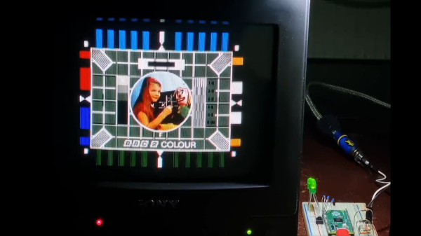
With the huge popularity of retrocomputing and of cyberdecks, we have seen a variety of projects that use a modern computer such as a Raspberry Pi bathed in the glorious glow of a CRT being used as a monitor. The right aesthetic is easily achieved this way, but there’s more to using a CRT display than simply thinking about its resolution. Particularly a black-and-white CRT or a vintage TV has some limitations due to its operation, that call for attention to the design of what is displayed upon it. [Jordan “Ploogle” Carroll] has taken a look at this subject, using a 1975 Zenith portable TV as an example.

The first difference between a flat panel and a CRT is that except in a few cases it has a curved surface and corners, and the edges of the scanned area protrude outside the edges of the screen. Thus the usable display area is less than the total display area, meaning that the action has to be concentrated away from the edges. Then there is the effect of a monochrome display on colour choice, in other words the luminance contrast between adjacent colours must be considered alongside the colour contrast. And finally there’s the restricted bandwidth of a CRT display, particularly when it fed via an RF antenna socket, which affects how much detail it can reasonably convey. The examples used are games, and it’s noticeable how Nintendo’s design language works well with this display. We can’t imagine Nintendo games being tested on black-and-white TV sets in 2022, so perhaps this is indicative of attention paid to design for accessibility.

While they require a bit of respect due to the presence of dangerous voltages, there’s a lot of fun to be had bringing a CRT into 2022. Get one while you still can, and maybe you could have a go at a retro cyberdeck.

Twitch And Blink Your Way Through Typing With This Facial Keyboard

For those that haven’t experienced it, the early days of parenthood are challenging, to say the least. Trying to get anything accomplished with a raging case of sleep deprivation is hard enough, but the little bundle of joy who always seems to need to be in physical contact with you makes doing things with your hands nigh impossible. What’s the new parent to do when it comes time to be gainfully employed?

Finding himself in such a boat, [Fletcher]’s solution was to build a face-activated keyboard to work around his offspring’s needs. Before you ask: no, voice recognition software wouldn’t work, at least according to the sleepy little boss who protests noisy awakenings. The solution instead was to first try OpenCV and the dlib facial recognition library to watch [Fletcher] blinking out Morse code. While that sorta-kinda worked, one’s blinkers can’t long endure such a workout, so he moved on to an easier set of gestures. Mouthing Morse code covers most of the keyboard, while a combination of eye, eyebrow, and other facial twitches and tics cover the rest, with MediaPipe’s Face Mesh doing the heavy-lifting in terms of landmark detection.

The resulting facial keyboard, aptly dubbed “CheekyKeys,” performed well enough for [Fletcher] to use for a skills test during an interview with a Big Tech Company. Imagining the interviewer on the other end watching him convulse his way through the interview was worth the price of admission, and we don’t even care if it was a put-on. Video after the break.

CheekyKeys is pretty cool, doing something with a webcam and Python that we thought would have needed a dedicated AI depth camera to accomplish. But perhaps the real hack here was how [Fletcher] taught himself Morse in fifteen minutes.

Continue reading “Twitch And Blink Your Way Through Typing With This Facial Keyboard”

A 3D Printed 35mm Movie Camera

Making a camera can be as easy as taking a cardboard box with a bit of film and a pin hole, but making a more accomplished camera requires some more work. A movie camera has all the engineering challenges as a regular camera with the added complication of a continuous film transport mechanism and shutter. Too much work? Not if you are [Yuta Ikeya], whose 3D printed movie camera uses commonly-available 35 mm film stock rather than the 8 mm or 16 mm film you might expect.

3D printing might not seem to lend itself to the complex mechanism of a movie camera, however with the tech of the 2020s in hand he’s eschewed a complex mechanism in favour of an Arduino and a pair of motors. The camera is hardly petite, but is still within the size to comfortably carry on a shoulder. The film must be loaded into a pair of cassettes, which are pleasingly designed to be reversible, with either able to function as both take-up and dispensing spool.

The resulting images have an extreme wide-screen format and a pleasing artistic feel. Looking at them we’re guessing there may be a light leak or two, but it’s fair to say that they enhance the quality rather than detract from it. Those of us who dabble in movie cameras can be forgiven for feeling rather envious.

We’ve reached out to him asking whether the files might one day be made available, meanwhile you can see it in action in the video below the break.

Continue reading “A 3D Printed 35mm Movie Camera”