[Angus] of Maker’s Muse has a video with a roundup of different 3D-printable hinge designs, and he points out that a great thing about 3D printing objects is that adding printable features to them is essentially free.
A great example of this is his experimental print-in-place butt hinge with indexing feature, which is a hinge that can lock without adding any additional parts. The whole video is worth a watch, but he shows off the experimental design at the 7:47 mark. The hinge can swing normally but when positioned just right, the squared-off pin within slots into a tapered track, locking the part in place.
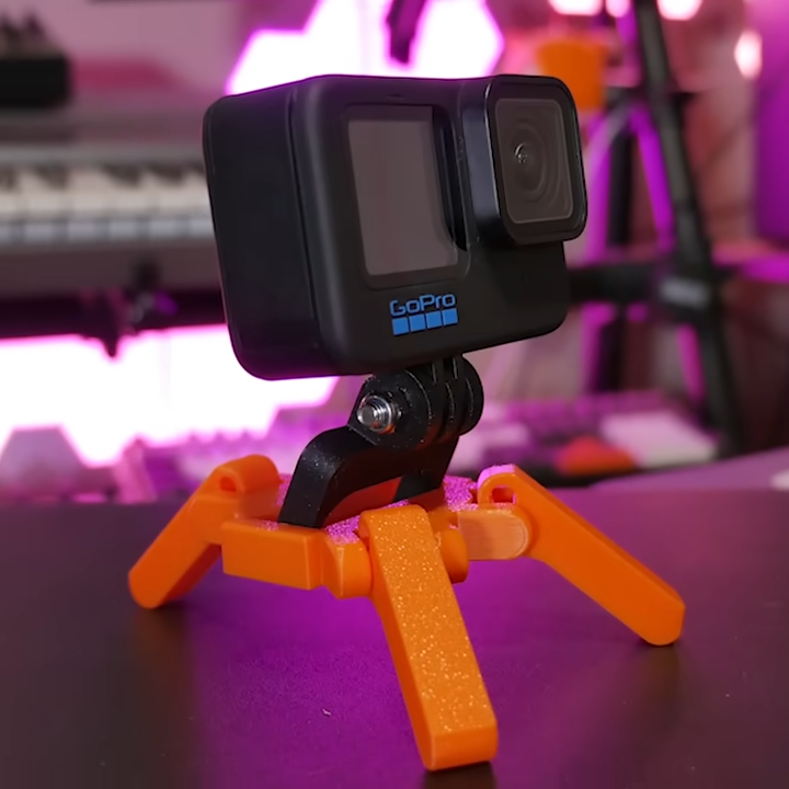
Inspired by a handheld shopping basket with a lockable handle, [Angus] worked out a design of his own and demonstrates it with a small GoPro tripod whose legs can fold and lock in place. He admits it’s a demonstration of the concept more than a genuinely useful tripod, but it does show what’s possible with some careful design. Being entirely 3D printed in a single piece and requiring no additional hardware is awfully nice.
3D printing is very well-suited to this sort of thing, and it’s worth playing to a printer’s strengths to do for pennies what one would otherwise need dollars to accomplish.
Want some tips on designing things in a way that take full advantage of what a 3D printer can achieve? Check out printing enclosures at an angle with minimal supports, leveraging the living hinge to print complex shapes flat (and fold them up for assembly), or even print a one-piece hinge that can actually withstand a serious load. All of those are full of tips, so keep them in mind the next time you design a part.


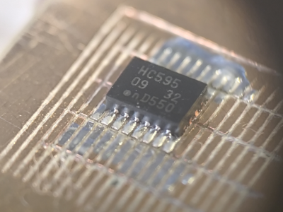 prevent the tool from chattering across the surface of the FR4 blank. Controlling and maintaining the rake angle was a critical parameter here. [Zach] actually took an additional step, which we likely wouldn’t have thought of, to have some copper blanks pre-fabricated to the required size and finished with an ENIG coating. It’s definitely a smart move!

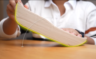
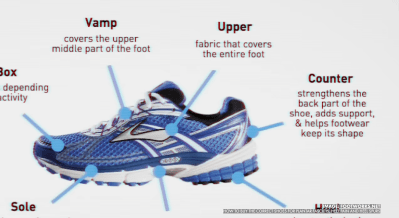 process, given that there is indeed a fair amount of science to shoe design. Firstly, after a quick run, the main issues with some existing shoes were identified, specifically that there are a lot of pain points; feet hurt from all the impacts, and knees take a real pounding, too. That meant they needed to increase the sole cushioning. They felt that too much energy was wasted with the shoes not promoting forward motion as much as possible; feet tended to bounce upwards so that a rocker sole shape would help. Finally, laces and other upper sole features cause distraction and some comfort issues, so those can be deleted.