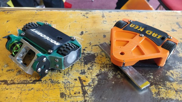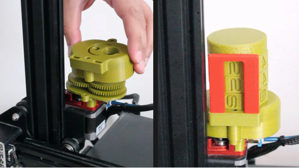
[ArduinoNmore] took an interesting approach to designing a counter intended to accurately display how many meters of filament a 3D printer has used. The Filamentmeter looks a little bit like a 3D printed handheld tally counter (or lap counter) but instead of a button to advance each digit, the readout represents how many meters of filament have gone through the extruder.
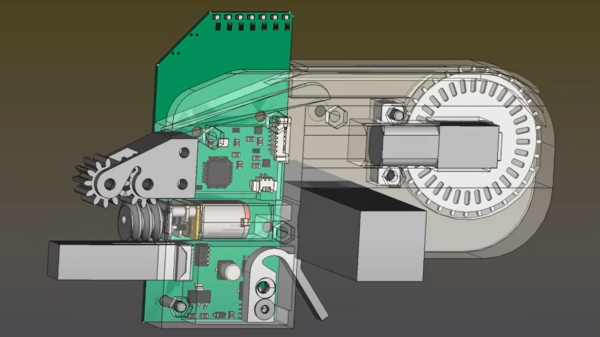
At first glance it may look like there is a motor hidden inside, or that the device is somehow sensing the filament directly. But it’s actually the movement of the extruder motor that drives the device. A small spur gear attached to the printer’s extruder drives a series of gears that advance the digits. This means that retractions — small reverses of the extruder motor during printing — are properly accounted for in the total, which is a nice touch.
[ArduinoNmore] designed this for the Ender 3, and the Filamentmeter relies on a specific extruder design and orientation to work properly. Of course, since it’s 3D printed, modifying the design for your own purposes should be pretty straightforward.
Curious? The design is being sold for a few bucks, and there is a free test piece one can print and use to confirm whether the design will work before mashing the buy button. Non-free printable 3D models can be a world of buyer beware, but test pieces and solid documentation are good ways to give buyers confidence in your work.
The insides of the unit are really quite intricate, with a clockwork-type elegance to them. You can see it all in the short video, embedded below.
Continue reading “The Filamentmeter: For When You Absolutely Want To Count Every Meter Used”