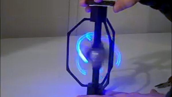
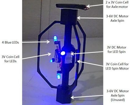
[Bithead] wanted to make a prop replica of an Electrostaff from Star Wars, but wasn’t sure how best to create the “crackling arcs of energy” effect at the business ends. After a few false starts, he decided to leverage the persistence of vision effect by spinning LEDs in more than one axis to create helical arcs of light and it seems that this method has some potential.
Many multi-axis persistence of vision devices use a component called a slip ring in order to maintain electrical connections across rotating parts, but [Bithead] had a simpler plan: 3D print a frame and give each axis its own battery. No centralized power source means a quicker prototype without any specialized parts, and therefore a faster proof of concept to test the idea.
[Bithead] already has improvements planned for a new version, but you can see the current prototype in action in the short video embedded after the break.
3D printing is well-suited to cranking out tank tread designs, because the numerous and identical segments required are a great fit for 3D printing’s strengths. The only hitch is the need for fasteners between each of those segments, but [AlwynxJones] has a clever solution that uses plentiful hard plastic spheres (in the form of 6 mm airsoft BBs) as both a fastener and a hinge between each of the 3D printed track segments.
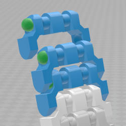
Each segment has hollows made to snugly fit 6 mm BBs (shown as green in the image here) which serve both as fasteners and bearing surfaces. Assembly requires a bit of force to snap everything together, but [AlwynxJones] judges the result worth not having to bother with bolts, wires, or other makeshift fasteners.
Bolts or screws are one option for connecting segments, but those are heavy and can get expensive. Segments of printer filament have been successfully used in other tread designs, though that method requires added work in the form of either pins, or heat deforming the filament ends to form a kind of rivet. This design may be a work in progress, but it seems like a promising and clever approach.
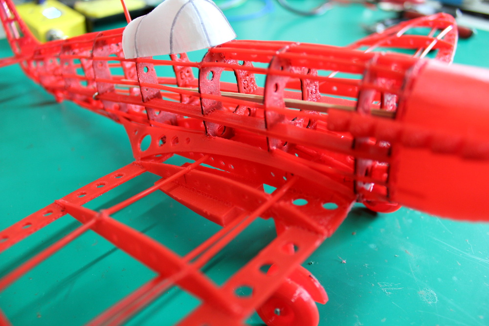
It used to be that if you wanted to make a nice scale model of an airplane, you’d be building the frame out of thin balsa ribs and covering it all up with tissue paper. Which incidentally was more or less how they built most real airplanes prior to the 1930s, so it wasn’t completely unreasonable to do the same on a smaller scale. But once injection molded plastics caught on, wood and tissue model kits largely went the way of the dodo.
[Marius Taciuc] wanted to share that classic model building experience with his son, but rather than trying to hunt down balsa kits in 2019, he decided to recreate the concept with modern techniques. His model of the Supermarine Spitfire, the vanguard of the British RAF during the Second World War, recreates the look of those early model kits but substitutes 3D printed or laser cut components for the fragile balsa strips of yore. The materials might be high-tech, but as evidenced by the video after the break, building the thing is still just as time consuming as ever.
Using a laser cutter to produce the parts would be the fastest method to get your own kit put together (you could even cut the parts out of balsa in that case), but you’ll still need a 3D printer for some components such as the propeller and cowling. On the other hand, if you 3D print all the parts like [Marius] did, you can use a soldering iron to quickly and securely “weld” everything together. For anyone who might be wondering, despite the size of the final plane, all of the individual components have been sized so everything is printable on a fairly standard 200 x 200 mm print bed.
While there’s no question the finished product looks beautiful, some might be wondering if it’s really worth the considerable effort and time necessary to produce and assemble the dizzying number of components required. To that end, [Marius] says it’s more of a learning experience than anything. Sure he could have bought a simplified plastic Spitfire model and assembled it with his son in an afternoon, but would they have really learned anything about its real-world counterpart? By assembling the plane piece by piece, it gives them a chance to really examine the nuances of this legendary aircraft.
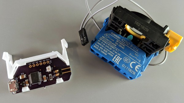
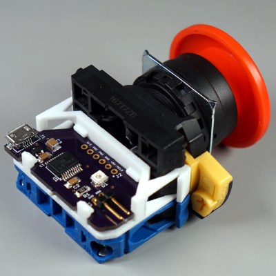
[Glen]’s project sounds perfectly straightforward: have a big industrial-style push button act as a one-key USB keyboard. He could have hacked something together in any number of ways, but instead he decided to create a truly elegant solution. His custom PCB mates to the factory parts perfectly, and the USB cable between the button and the computer even fits through the button enclosure’s lead hole.
It turns out that industrial push buttons have standardized components which can be assembled in an almost LEGO-like manner, with components mixed and matched to provide different switch actions, light indicators, and things of that nature. [Glen] decided to leverage this feature to make his custom PCB (the same design used in his one-key keyboard project) fit just like a factory component. With a 3D printed adapter, the PCB locks in just like any other component, and even lines up with the lead hole in the button’s enclosure for easy connecting of the USB cable.
What does [Glen] use the big button for? Currently he has two applications: one provides a simple, one-button screen lock on a Linux box running a virtual machine at his place of work. It first disengages the keyboard capture of the virtual machine, then engages the screen lock on the host. The other inserts a poop emoji into Microsoft documents. Code and PCB design files for [Glen]’s small keyboards are available on GitHub.
Anansi in African folktale is a trickster and god of stories, usually taking physical form of a spider. Anansi’s adventures through oral tradition have adapted to the situation of people telling those stories, everything ranging from unseasonable weather to living a life in slavery. How might Anansi adapt to the twenty-first century? [odd_jayy] imagined the form of a cyborg spider, and created Asi the robot companion to perch on his shoulder. Anyone who desire their own are invited to visit Asi’s project page.
Asi was inspired by [Alex Glow]’s Archimedes, who also has a project page for anyone to build their own. According to [Alex] at Superconference 2018, she knew of several who have done so, some with their own individual customization. [odd_jayy] loved the idea of a robot companion perched on his shoulder but decided to draw from a different pool of cultural folklore for Asi. Accompanying him to various events like Sparklecon 2019, Asi is always a crowd pleaser wherever they go.
Like every project ever undertaken, there is no shortage of ideas for Asi’s future and [odd_jayy] listed some of them in an interview with [Alex]. (Video after the break.) Adding sound localization components will let Asi face whoever’s speaking nearby. Mechanical articulation for legs would allow more dynamic behaviors while perched, but if the motors are powerful enough, Asi can walk on a surface when not perched. It’s always great to see open source projects inspire even more projects, and watch them as they all evolve in skill and capability. If they all become independently mobile, we’ll need clarification when discussing the average velocity of an unladen folklore robot companion: African or European folklore?
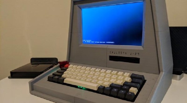
The Fallout series of video games provide a wonderful alternative history that answers the question of what might have happened had the microchip never been invented. Yes, most things run on tubes, and apparently you can implement an AI that passes a Turing test in tubes (does the Turing test apply if you’re comparing it against NPCs?). Of course, as with all of computer history, the coolest parts of Fallout are the computer terminals, so [Pigeonaut] decided to build one. All the files are available, and if you have a Pi sitting around this is a good weekend project.
This terminal has a host of features that are well-suited for the modern vault dweller. Of note, the entire case is 3D printed, in multiple pieces. Sure, considering the display is an LCD it’s a tiny bit thick, but you don’t get the Atomic age aesthetic without a big CRT, do you? The keyboard is a standard, off-the-shelf mechanical keyboard for clicky goodness with vintage-style keycaps. There’s a 3.5″ USB floppy drive, because there’s nothing that will survive a nuclear holocaust like magnetic media. The rest of the build is a Raspberry Pi 3B+, which is more than enough compute power to open a door shaped like a gear.
As for what you would do with a retro-inspired Pi terminal, well, it would make a good computer for the workbench, and since the case is already designed for a 3.5″ drive, you could use this to archive some old media. If there’s one thing the apocalypse tells us, it’s that these old terminals will still be kicking after a few hundred years.
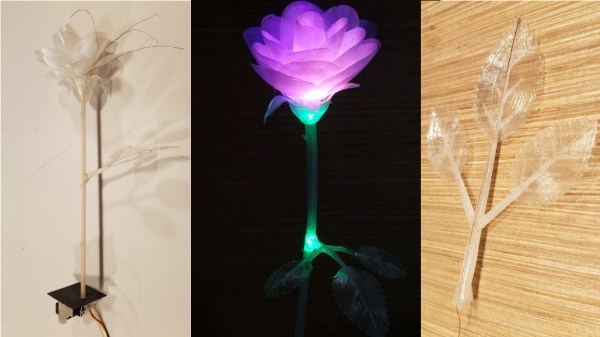
Inspiration runs on its own schedule: great ideas don’t always arrive in a timely manner. Such was the case with [Daren Schwenke]’s notion for creating a 3D-printed blooming rose for his valentine, a plan which came about on February 13. Inspired by [Jiří Praus]’s animated wireframe tulip, [Daren] figured he could make a rose from clear printed petals colored by RGB LEDs. 24 hours seemed tight but sufficient, so he diligently set to work, but – after a valiant effort – finally had to extend the schedule. It’s now more than a month later, and tweaks to the design continue, but the result is nothing short of spectacular.
We first saw a discussion of the idea over on Hack Chat, and followed as it evolved into a project on hackaday.io. There, you can read the full details of the trials and tribulations that had to be endured to make this project happen. From a printer that wouldn’t boot, through testing PLA, TPU, and nylon filament, trying a number of different approaches for springs and hinges to operate the petals, and wiring the delicate DotStar LEDs with magnet wire, you can get a really good sense of the amount of experimentation it takes to complete a project like this. If you know anyone who still thinks 3D printing is as easy as clicking a button, send them over to read the logs on this project.
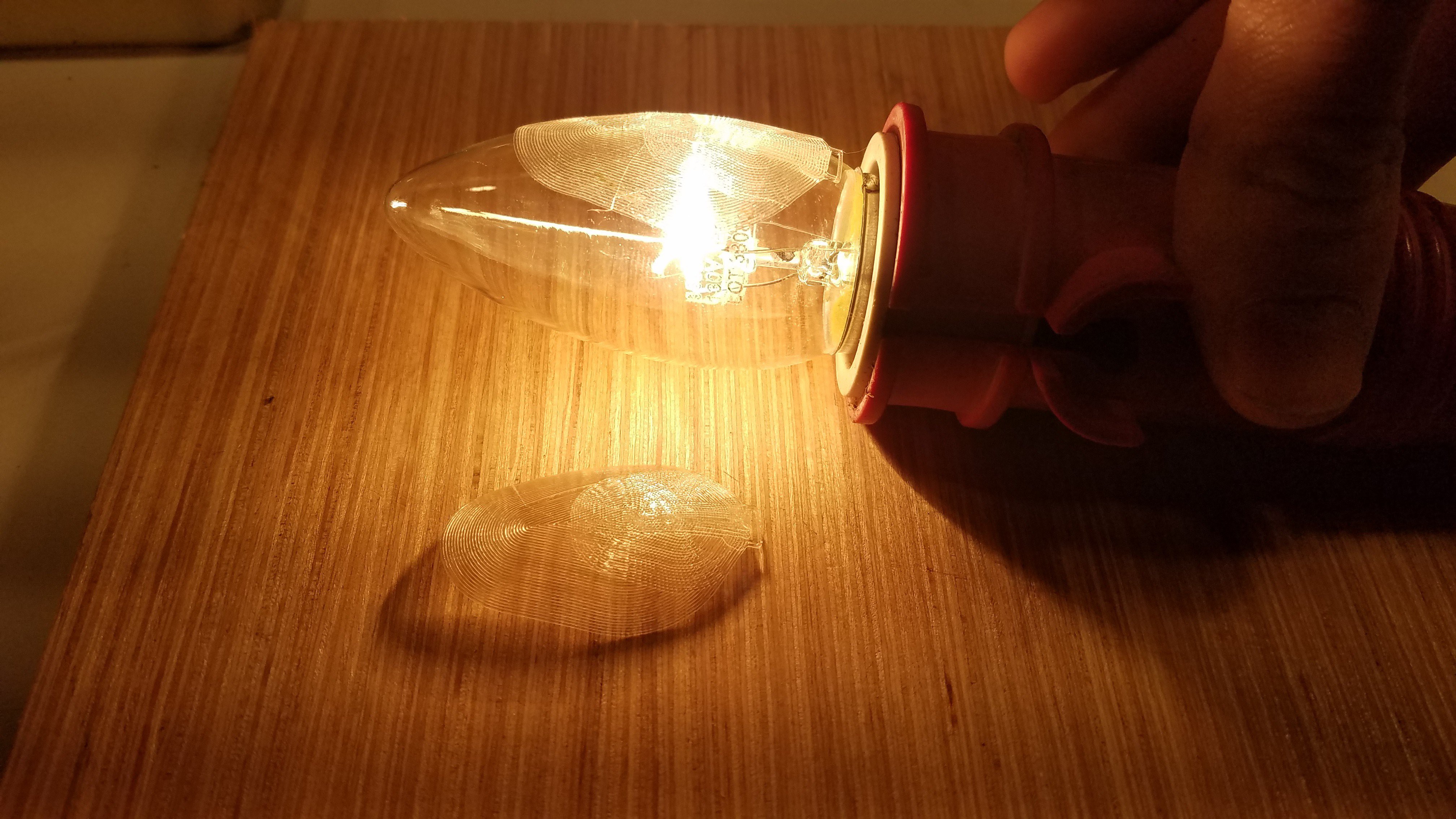
An early try at forming PLA petals
What finally materialized is a terrific combination of common hacker technologies. The petals are printed flat in nylon, then formed over a hot incandescent chandelier bulb. The stem and leaves are also printed, but the side stem has a piece of magnet wire embedded in the print as a capacitive touch sensor; when the leaf is touched, the rose blossom opens or closes. Magnet wire for the LEDs and a connecting rod for the mechanics run through the main stem to the base, where a 9g servo is responsible for controlling the bloom. The whole thing is controlled, naturally, with an Arduino. To move the project along a little more quickly, [Daren] enlisted the help of another Hack Chat denizen, [Morning.Star], who did an amazing job on the software without any access to the actual hardware.
Be sure to check out the video of the rose in action, after the break.
 [Bithead] wanted to make a prop replica of an Electrostaff from Star Wars, but wasn’t sure how best to create the “crackling arcs of energy” effect at the business ends. After a few false starts, he decided to leverage the persistence of vision effect by spinning LEDs in more than one axis to create helical arcs of light and it seems that this method has some potential.
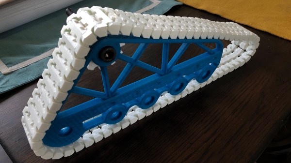
 Each segment has hollows made to snugly fit 6 mm BBs (shown as green in the image here) which serve both as fasteners and bearing surfaces. Assembly requires a bit of force to snap everything together, but [AlwynxJones] judges the result worth not having to bother with bolts, wires, or other makeshift fasteners.
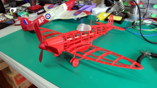
 It turns out that industrial push buttons have standardized components which can be assembled in an almost LEGO-like manner, with components mixed and matched to provide different switch actions, light indicators, and things of that nature. [Glen] decided to leverage this feature to make his custom PCB (the same design used in his