Remember that time a giant cylindrical aquarium in a Berlin hotel bar catastrophically failed and left thousands of fish homeless? We sure do, and further recall that at the time, we were very curious about the engineering details of how this structure failed so spectacularly. At the time, we were sure there’d be plenty of follow-up on that score, but life happened and we forgot all about the story. Luckily, a faithful reader named Craig didn’t, and he helpfully ran down a few follow-up articles that came out last year that are worth looking at.
The first is from prosecutors in Berlin with a report offering three possibilities: that the adhesive holding together the acrylic panels of the aquarium failed; that the base of the tank was dented during recent refurbishment; or that the aquarium was refilled too soon after the repairs, leading to the acrylic panels drying out. We’re a little confused by that last one just from an intuitive standpoint, but each of these possibilities seems hand-wavy enough that the report’s executive summary could have been “Meh, Scheiße happens.”
[Julius Curt] needed to mark acrylic panels with a bit more clarity than the usual way of rastering the surface, so they attempted to 3D print directly to an acrylic sheet, which worked perfectly. The obvious way to do this was to bond the acrylic sheet to the bed with glue temporarily, but another way was tried, and it’s much less messy and precarious.
The bond between a 3D print and acrylic is very strong
The first step was to create a 3D model which combined a constraining ‘fence’ to contain the acrylic panel with the required artwork floating above. It was easy enough to run the print long enough to build the fence, then pause the print mid-way to add the pristine panel and restart after a quick re-prime and wipe.
There were a few simple takeaways from the video below. First, to ensure sufficient tolerance between the fence and the panel, consider the layer width (plus associated tolerance when printed) and the laser kerf of your machines to ensure a not-too-sloppy fit. Secondly, that hot nozzle won’t do the acrylic surface any favours during travel moves, so enabling Z-hopping is essential!
Another use for this simple technique is to fully incorporate an acrylic sheet within a print by pausing at an appropriate height again, dropping the panel in, and continuing the print. A degree of overlap will lock the panel tight, with the plastic bonding very firmly to the acrylic, as [Julius] demonstrates in the video.
It’s always a delight to see how techniques can combine to create the desired effects. Here’s how to use a color laser printer and toner transfer paper to apply designs to a 3D printing front panel. Whilst we’re thinking about the multitude of uses for hacking with acrylic, what about not doing that and using corrugated plastic instead?
We (well, some of us) are complete suckers for things that are both much smaller and much larger than life. And if that thing actually does what its supposed to? Squee! So naturally, we rushed to bring you news of this mini NUC rack designed by [Jeremy Weatherford].
Inspiration comes from a lot of places, often times from stuff that lives on your desk. [Jeremy] had a pile of NUCs and thought they resembled a mini rack already, so why not build them one to live in? It was the perfect excuse to learn CAD, so off [Jeremy] went. Although this is a mini rack, the parts were too big to print. Another opportunity presented itself, and [Jeremy] tried out an online service to get the acrylic cut.
Assembly may have been fiddly with super glue all over the nice black acrylic, but [Jeremy] learned an important tip: excess glue can be removed with vegetable oil. Once it was built, he decided to make it into a control system lab and even found a perfect little five-port switch to top it off. The logo plate, of course, is the icing on this cake.
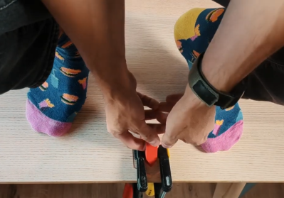
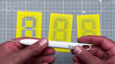
Displays are crucial to modern life; they are literally everywhere. But modern flat-panel LCDs and cheap 7-segment LED displays are, well, a bit boring. When we hackers want to display the progress of time, we want something more interesting, hence the plethora of projects using Nixie tubes and various incantations of edge-lit segmented units. Here is [upir] with their take on the simple edge-lit acrylic 7-segment design, with a great video explanation of all the steps involved.
Engraving the acrylic sheets by hand using 3D printed stencils
The idea behind this concept is not new. Older displays of this type used tiny tungsten filament bulbs and complex light paths to direct light to the front of the display. The modern version, however, uses edge-lit panels with a grid of small LEDs beneath each segment, which are concealed within a casing. This design relies on the principle of total internal reflection, created by the contrast in refractive indices of acrylic and air. Light entering the panel from below at an angle greater than 42 degrees from normal is entirely reflected inside the panel. Fortunately, tiny LEDs have a wide dispersion angle, so if they are positioned close enough to the edge, they can guide sufficient light into the panel. Once this setup is in place, the surface can be etched or engraved using a CNC machine or a laser cutter. A rough surface texture is vital for this process, as it disrupts some of the light paths, scattering and directing some of it sideways to the viewer. Finally, to create your display, design enough parallel-stacked sheets for each segment of the display—seven in this case, but you could add more, such as an eighth for a decimal point.
How you arrange your lighting is up to you, but [upir] uses an off-the-shelf ESP32-S3 addressable LED array. This design has a few shortcomings, but it is a great start—if a little overkill for a single digit! Using some straightforward Arduino code, one display row is set to white to guide light into a single-segment sheet. To form a complete digital, you illuminate the appropriate combination of sheets. To engrave the sheets, [upir] wanted to use a laser cutter but was put off by the cost. A CNC 3018 was considered, but the choice was bewildering, so they just went with a hand-engraving pick, using a couple of 3D printed stencils as a guide. A sheet holder and light masking arrangement were created in Fusion 360, which was extended into a box to enclose the LED array, which could then be 3D printed.
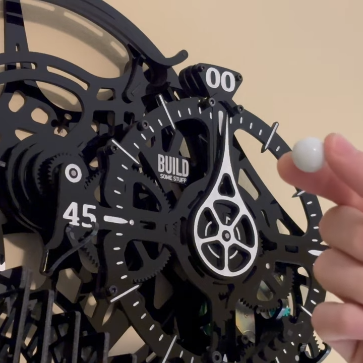
[Kelton] from Build Some Stuff decided to create a clock that not only had kinetic elements, but a healthy dose of Rube Goldberg inspiration. The result is a work in progress, but one that looks awfully promising.
The main elements of the design are rotating pieces that indicate the hours and minutes, but each hour is advanced solely by the satisfying physical culmination of multiple interacting systems. Those systems also completely reset themselves every hour.
Each hour, a marble run kicks off a short chain reaction that culminates in advancing the hour.
At the top of the hour, a marble starts down a track and eventually tips over a series of hinged “dominoes”, which culminate in triggering a spring-loaded ratchet that advances the hour. The marble then gets carried back to the top of the device, ready for next time. Meanwhile, the domino slats and spring-loaded ratchets all get reset by a pulley system.
There’s still some work to do in mounting the motor, pulley system, and marble run. Also, a few bugs have surfaced, like a slight overshoot in the hour display. All par for the course for a device with such a large number of moving parts, we suppose.
[Kelton] has a pretty good sense how it will all work in the end, and it looks promising. We can’t wait to see it in its final form, but the tour of clock so far is pretty neat. Check it out in the video, embedded just under the page break.
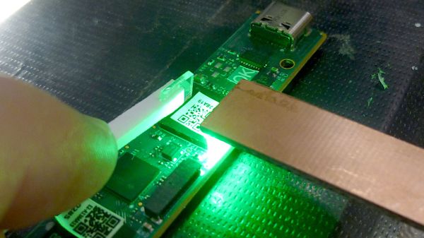
Compared to through-hole construction, inspecting SMD construction is a whole other game. Things you thought were small before are almost invisible now, and making sure solder got where it’s supposed to go can be a real chore. Add some ball grid array (BGA) chips into the mix, where the solder joints are not visible by design, and inspection is more a leap of faith than objective proof of results.
How it works.
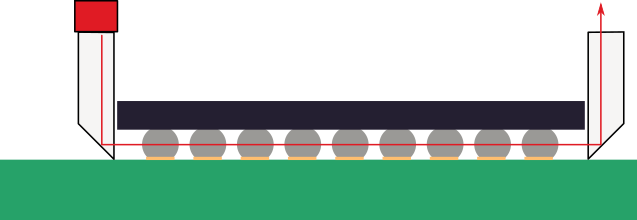
Unless, of course, you put the power of optics to work, as [Petteri Aimonen] does with this clever BGA inspection tool. It relies on a pair of tiny prisms to bounce light under one side of a BGA chip and back up the other. The prisms are made from thin sheets of acrylic; [Petteri] didn’t have any 1-mm acrylic sheet on hand, so he harvested material from a razor blade package. The edge of each piece was ground to a 45-degree angle and polished with successively finer grits until the surfaces were highly reflective. One prism was affixed to a small scrap of PCB with eleven SMD LEDs in a row, forming a light pipe that turns the light through 90 degrees. The light source is held along one edge of a BGA, shining light underneath to the other prism, bouncing light through the forest of solder balls and back toward the observer.
The results aren’t exactly crystal clear, which is understandable given the expedient nature of the materials and construction employed. But it’s certainly more than enough to see any gross problems lying below a BGA, like shorts or insufficiently melted solder. [Petteri] reports that flux can be a problem, too, as excess of the stuff can crystalize between pads under the BGA and obstruct the light. A little extra cleaning should help in such cases.
Haven’t tackled a BGA job yet? You might want to get up to speed on that.
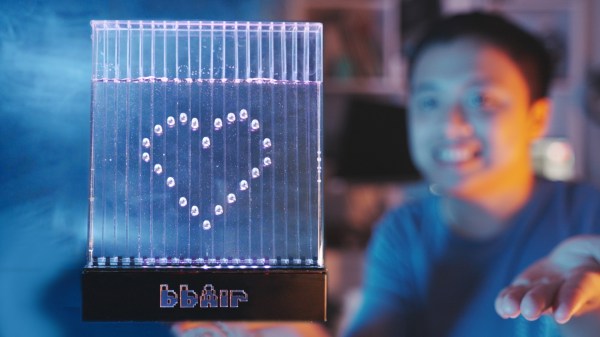
We all have good intentions when starting a new project, but then again, we all know where those lead. Such is the case with [RealCorebb]’s BBAir project, a completely transparent air bubble display. Although the plan was to spend about three months on it, the months slowly added up to a full year of tinkering.
It all started when [RealCorebb] made a subscriber counter using Minecraft campfire smoke to display the digits. Someone suggested using air to implement the next iteration, and for [RealCorebb], it was challenge accepted. After considering a syringe for each channel, a separate pump, or one pump and many solenoids, [RealCorebb] settled on solenoids to push air, and designed a PCB to reduce the amount of wire spaghetti.
Once [RealCorebb] created an acrylic enclosure and wired everything up, it was time to test it out. Everything worked, except that air was leaking from somewhere, which turned out to be the way the solenoids were installed. Then, of course, it was time to don sunglasses and write the code. We still don’t know if [RealCorebb] settled on water, glycerine, or silicone oil, but the end result is quite nice, and we’re betting on glycerine. Be sure to check out the build video after the break, which has English subtitles.