Low Power And Pin-Constrained

We’ve all been there. You’re building up a microcontroller project and you wish that you could just add “one more feature” but you’re limited by the hardware. Time to start thinking. (Or, arguably, buy the next model up.)

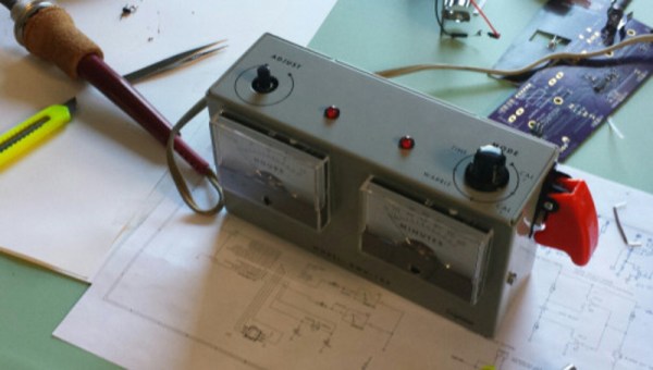
[Sam Feller] found himself in this position, adding a knob to set the time and a button to arm the alarm for his Analog Voltmeter Clock, and he came up with a way to implement an on-off switch, and poll a button and a potentiometer with only two pins of a microcontroller.

The problem with potentiometers in low-power designs is that they’re always leaking power. That is, unless you switch them off when you’re not using them. So the ideal solution is to power the potentiometer from one GPIO pin on the microcontroller, and read its value with another. That’s two GPIO pins just for the potentiometer. But [Sam] needed to read input from a button too, and he was out of pins.

His clever solution is to switch two resistors in or out of the circuit depending on the status of the pushbutton, so that the voltage range at the potentiometer is between either VCC and VCC/2 when the switch is pressed, or between VCC/2 and GND when the switch is not pressed.

If the ADC reads something higher than VCC/2, the microcontroller knows that the button is pressed, and vice-versa. The potentiometer’s setting determines exactly where the voltage lies within either range.

Done and done. If you find yourself in the similar situation of needing to read in values from a whole bunch of buttons instead of a potentiometer, then you can try using an R-2R DAC wired up to the pushbuttons and reading the (analog) value to figure out which buttons are pressed. (If you squint your eyes just right, this solution is the same as the R-2R DAC one with the potentiometer replacing all but the most-significant bit of the R-2R DAC.)

Another tool for the toolbox. Thanks [Sam].

Video FPGA With No External A/D

You have an old PC with a nonstandard RGB video out and you need to bring it to a modern PAL TV set. That’s the problem [svofski] had, so he decided to use an Altera-based DE1 board to do the conversion. Normally, you’d expect reading an RGB video signal would take an analog to digital converter, which is not typically present on an FPGA. Instead of adding an external device, [svofski] used a trick to hijack the FPGA’s LVDS receivers and use them as comparators.

Continue reading “Video FPGA With No External A/D”

RaspiDrums Uses Expensive Sensors

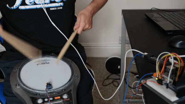
Piezoelectric sensors are great for monitoring mechanical impacts with a microcontroller. Whether you’re monitoring knocks on a door or watching a heartbeat, they are a cheap way to get the job done. They do have their downsides, though, so when [Jeremy] wanted to build an electronic drum set, he decided to use more expensive accelerometers to measure the percussive impacts instead.

Even though piezo sensors are cheap, they require a lot of work to get them working properly. The ADXL377 3-axis accelerometer that [Jeremy] found requires much less work, plus provides more reliable data due to a 1kHz low-pass filter at the output. In his setup, a Raspberry Pi handles all of the heavy lifting. An ADC on each drum sends data about each impact of the drum, and the Raspberry Pi outputs sound via the native Alsa driver and a USB sound card.

This project goes a long way to show how much simpler a project like this is once you find the right hardware for the job. [Jeremy]’s new electronic drums are very well documented as well if you are curious about using accelerometers on your newest project rather than piezo sensors. And, if you’re into drums be sure to see how you can have drums anywhere, or how you can build your own logic drums.

Continue reading “RaspiDrums Uses Expensive Sensors”

Fast ADC Uses Old School Scope Hack For 48 MSPS

[Carlos] needed an ADC with a 50 nanosecond sample period for his laser lab, that’s 20Msps! (20 million samples a second). While in recent years, commodity ADCs reaching into the low GSPS have become available, integrated acquisition systems are still somewhat expensive. So [Carlos] decided to do what every good hacker does, and built his own solution. His project post pretty much just links to a whitepaper he wrote (PDF) so we’ll try and boil it down for you:

In order to simplify development [Carlos] borrowed a technique commonly used in the first era of digital oscilloscopes, Equivalent Sampling Time.

est

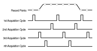
The figure to the right is from the TDS460 manual. While it may seem counter intuitive to those only familiar with modern scopes, the TDS460 achieved a 400MHz bandwidth using a 100MSPS ADC. In order to achieve this the scope acquires a single trace in multiple cycles, each time offsetting the acquisitions as shown and combining the result.

In this way, early digital scope developers could sidestep the limitations of the available ADCs to achieve a higher effective bandwidth. However there is of course one catch: the technique only works for periodic signals.

This was fine for [Carlos] who implemented a technique on a Cypress PSoC 4, which provides analog FPGA-like functionality. By offsetting the ADC trigger he has able to achieve an EST of 48MHz using a ADC sampling at 1MHz. If you want a little help getting into PSOC 4 yourself, check out the guide that [Bil Herd] made.

Neat hack [Carlos] and we hope to hear more about your laser lab in the future.

Auto-sleep Hacked In PC Speakers

We can commiserate with [HardwareCoder] who would rather not leave his PC speakers on all the time. The Creative T20 set that he uses turn off when you turn the volume knob all the way down until it clicks. So shutting them off means repositioning the volume each time they’re switched on again. This hack kills two birds with one stone by turning on and off automatically without touching that knob.

The system is based around an ATtiny45 and a few other simple components. It uses two ADCs to monitor the rear input channels of the PC speakers. If no sound is detected for more than one minute, the shutdown pin of the speakers’ amp chip is triggered. That’s not quite where the hack ends. We mentioned it monitors the rear input of the speakers, but it doesn’t monitor the front AUX input. An additional push button is used to disable the auto-sleep when using this front input. There is also a fancy PWM-based heartbeat on an LED when the speakers are sleeping.

[HardwareCoder] was worried that we wouldn’t be interested in this since it’s quite similar to a hack we ran a few years ago. We hope you’ll agree it’s worth another look. He also warned us that the demo video was boring. We watched it all anyway and can confirm that there’s not much action there but we embedded it below anyway.

Continue reading “Auto-sleep Hacked In PC Speakers”

When Adding Noise Helps

It’s a counterintuitive result that you might need to add noise to an input signal to get the full benefits from oversampling in analog to digital conversion. [Paul Allen] steps us through a simple demonstration (dead link, try Internet Archive) of why this works on his blog. If you’re curious about oversampling, it’s a good read.

Oversampling helps to reduce quantization noise, which is the sampling equivalent of rounding error. In [Paul’s] one-bit ADC example, the two available output values are zero volts and one volt. Any analog signal between these two values is rounded off to either zero or one, and the resulting difference is the quantization error.

In oversampling, instead of taking the bare minimum number of samples you need you take extra samples and average them together. But as [Paul] demonstrates, this only works if you’ve got enough noise in the system already. If you don’t, you can actually make your output more accurate by adding noise on the input. That’s the counterintuitive bit.

We like the way he’s reduced the example to the absolute minimum. Instead of demonstrating how 16x oversampling can add two bits of resolution to your 10-bit ADC, it’s a lot clearer with the one-bit example.

[Paul’s] demo is great because it makes a strange idea obvious. But it got us just far enough to ask ourselves how much noise is required in the system for oversampling to help in reducing quantization noise. And just how much oversampling is necessary to improve the result by a given number of bits? (The answers are: at least one bit’s worth of noise and 22B, respectively, but we’d love to see this covered intuitively.) We’re waiting for the next installment, or maybe you can try your luck in the comment section.

Digital To Analog To Digital To Analog To Digital Conversion

[Andy] had the idea of turning a mixing desk into a MIDI controller. At first glance, this idea seems extremely practical – mixers are a great way to get a lot of dials and faders in a cheap, compact, and robust enclosure. Exactly how you turn a mixer into a MIDI device is what’s important. This build might not be the most efficient, but it does have the best name ever: digital to analog to digital to analog to digital conversion.

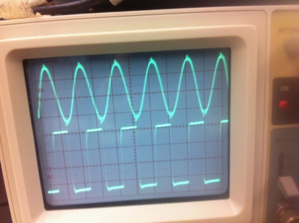
The process starts by generating a sine wave on an Arduino with some direct digital synthesis. A 480 Hz square wave is generated on an ATTiny85. Both of these signals are then fed into a 74LS08 AND gate. According to the schematic [Andy] posted, these signals are going into two different gates, with the other input of the gate pulled high. The output of the gate is then sent through a pair of resistors and combined to the ‘audio out’ signal. [Andy] says this is ‘spine-crawling’ for people who do this professionally. If anyone knows what this part of the circuit actually does, please leave a note in the comments.

The signal from the AND gates is then fed into the mixer and sent out to the analog input of another Arduino. This Arduino converts the audio coming out of the mixer to frequencies using a Fast Hartley Transform. With a binary representation of what’s happening inside the mixer, [Andy] has something that can be converted into MIDI.

[Andy] put up a demo of this circuit working. He’s connected the MIDI out to Abelton and can modify MIDI parameters using an audio mixer. Video of that below if you’re still trying to wrap your head around this one.

Continue reading “Digital To Analog To Digital To Analog To Digital Conversion”